Autopapyrus · Chevrolet Corsica 1st Generation
https://autopapyrus.com/guides/chevrolet/corsica/wiring-diagram-and-main-components-reference/
https://autopapyrus.com/guides/chevrolet/corsica/wiring-diagram-and-main-components-reference/
Compiled automatically from service literature and owner experience. Specs are for the typical configuration — check them against your exact car before you start.
Chevrolet Corsica 1st Generation: Wiring Diagram and Main Components Reference
The 1989 Chevrolet Corsica with the 2.8L V6 LB6 engine uses a multiport fuel-injected engine management system and a 12-pin ALDL diagnostic connector. The wiring system includes a main fuse block inside the cabin, fusible links under the hood, and a network of ground points on the engine block and body.
Part
- 🔩 if replacement is needed: fuses (as per rating), fuel pump relay, ignition relay, fusible links
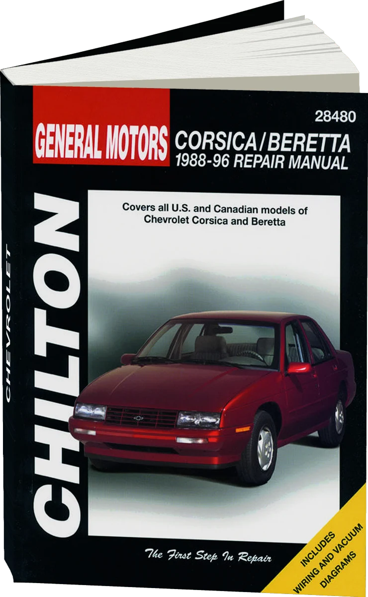 There's a full repair manual for this car
Every system, wiring diagrams and torque specs — not just this job. Chilton and 2 more.
See manuals →
Step by step
7 steps- Fuse block in the cabin: it is located on the left side under the instrument panel and is visible with the driver's door open. The main circuits are protected by individual fuses: position 1 (15 A) is the engine control module and injectors, position 2 (20 A) is the brake lights and hazard warning lights, and positions 7 and 11 are fed from a common fusible link. In addition, 1-2 inline fuses for individual systems may be installed under the steering column.
- Fusible links: they are installed at the starter terminal on the positive battery cable. There are three links: two feed the charging system (alternator) and the third feeds the main fuse block. In an overload or short circuit, the link melts before the main wire does. It looks like a thickened section of wire with insulation of a different color. Check it for an open circuit with a multimeter, with the ignition off.
- Main ground points: the negative battery terminal is connected to the engine block by a thick black cable. The second ground point is a braided strap from the engine block to the body firewall (left side of the engine, near the engine mount). Additional points are the engine control module ground on a stud under the intake manifold, and the headlight and turn signal ground on the front frame rail. If you have starting problems or the engine runs erratically, check all ground points for tightness and corrosion.
- ALDL diagnostic connector: it has 12 pins and is located under the instrument panel on the left side of the driver (usually near the door sill or next to the fuse block). Terminal A is ground and terminal B is diagnostic enable. To read the engine trouble codes: turn the ignition key to ON (do not start the engine), then connect terminals A and B with a jumper wire. The Check Engine light on the instrument panel will start flashing: a series of long flashes (tens), followed by short ones (units). Code 12 (one long flash, two short) is the normal diagnostic mode and is repeated three times at the start.
- Wire color coding: it follows the late-1980s GM standard. Black is ground, red is battery positive (unprotected), orange or pink is positive through the ignition switch, brown is parking lights, yellow is left turn signal, dark green is right turn signal, white is brake lights, and purple is engine management sensor circuits. Each wire may have an additional stripe (tracer) to tell it apart within the harness.
- Relays and their locations: the main relays (fuel pump, ignition, cooling fan) are usually mounted near the fuse block or on the engine compartment bulkhead. The fuel pump relay is energized for 2-3 seconds when the ignition is turned on to build up pressure. A faulty relay shows up as no pump hum when you turn the key. To test it, bridge the relay contacts directly or swap in a similar relay.
- Connectors: the wiring harness passes through the engine compartment bulkhead in several places, and the main connector C100 (bulkhead connector) is on the left side of the firewall. Pin assignments depend on equipment (climate control, cruise control, automatic transmission). When diagnosing electrical faults, check the condition of the contacts in the connectors for corrosion, moisture and loose terminals.
Common mistakes and warnings
- Before disconnecting the battery terminal, make sure the radio's unlock code is saved (if an anti-theft code is installed). Do not short the battery positive directly to ground, because the fusible links may not blow instantly and the wiring could catch fire. When working on the electrical system, use a multimeter to check voltage and circuit continuity. Do not rely on visual inspection.