Autopapyrus · Geely Emgrand 1.5 (4G15) (2013)
https://autopapyrus.com/guides/geely/emgrand/engine-overhaul/
https://autopapyrus.com/guides/geely/emgrand/engine-overhaul/
Compiled automatically from service literature and owner experience. Specs are for the typical configuration — check them against your exact car before you start.
Geely Emgrand 1.5 (4G15) (2013): Engine Overhaul
An overhaul of the 1.5 (4G15) engine includes complete disassembly, inspection of the block, crankshaft and cylinder head, boring and honing the cylinders for oversize pistons, grinding the crankshaft journals if worn, and reassembly with new bearings and rings. Exact factory specifications, clearances and torque values for this engine are not confirmed in publicly available sources. Below are the general procedure and typical ranges. Always verify final values against the engine manufacturer's service manual.
Part
- 🔩 piston set with rings and wrist pins (standard or oversize +0.25/+0.50/+1.0 mm, depending on the block measurements), connecting rod and main bearing set (standard or undersize), crankshaft thrust washers, full engine gasket set, cylinder head gasket, cylinder head bolts (single-use), valve stem seals, crankshaft seals, timing belt or chain with tensioner/idler pulleys and water pump, oil pump (depending on condition), engine oil and filter, coolant. Part numbers are not given to avoid errors: select parts by name, make and size
Step by step
21 steps- Preparation. Disconnect the battery, drain the oil and coolant, and remove the engine undercover. Before disassembly, photograph the wiring and hose routing and label the connectors. Relieve the fuel system pressure.
- Removing accessories and pulling the engine. Remove the air filter with its ducts, radiator, drive belts, alternator, A/C compressor (do not open the refrigerant circuit; move it aside), starter, and exhaust manifold with catalytic converter. Separate the transmission from the engine, check the engine mounts, and lift the powertrain out upward or lower it out downward. The order depends on the trim and equipment, so work as the situation requires.
- Mounting on the stand and external disassembly. Remove the clutch and flywheel (replace the flywheel bolts before installation, or treat them with thread locker). Remove the intake manifold, fuel rail with injectors, ignition coils and spark plugs.
- Removing the timing drive. Set the marks to TDC of cylinder 1, remove the covers, the belt (chain), tensioner and idler pulleys, and the camshaft pulleys. Photograph the marks. Put marks on the crankshaft and camshafts so you don't make a mistake later.
- Removing the cylinder head. Loosen the cylinder head bolts in sequence from the outside toward the center, in 2-3 stages, with the engine cold. Remove the head and gasket. Lay out the valve train parts (lifters or rocker arms) strictly in order so they are not mixed up during assembly.
- Disassembling the lower end. Turn the engine over and remove the oil pan, oil pickup and oil pump. Before removing the connecting rods, number the rod caps and the rods themselves. Unbolt the rod caps, push the pistons up out through the cylinders, and keep the bearings with their respective caps separate so you can assess wear.
- Removing the crankshaft. Number the main bearing caps, loosen the bolts gradually in 2-3 passes from the outside toward the center, then remove the caps and the crankshaft. Remove the bearings and the thrust washers.
- Cleaning and inspecting the block. Remove the oil gallery plugs, wash the block and clean the passages with brushes. Inspect for cracks and scoring. Measure the cylinders with a bore gauge at 3 levels and in 2 planes. If wear or out-of-roundness exceeds the limit (guideline: out-of-roundness above 0.03-0.05 mm; working clearances per the engine specifications), the cylinders are bored to the oversize piston size. Sleeving is acceptable if the block is aluminum with pressed-in liners (check the block type for this engine when you disassemble it).
- Boring and honing. The block goes to the machine shop together with the purchased pistons. Boring is done to the actual piston size with the clearance specified by the manufacturer (guideline for gasoline engines of this class: 0.02-0.05 mm; the exact value is given by the piston manufacturer). After boring, a finish hone is done with a crosshatch angle of about 45-60 degrees. Then the block is thoroughly washed again with soap and water and oiled.
- Inspecting the crankshaft. Measure the main and rod journals with a micrometer, assess out-of-roundness and taper, and check the shaft runout. If worn, the journals are ground to the undersize of the bearings (usually in 0.25 mm steps). After grinding, be sure to flush the oil passages.
- Inspecting the cylinder head. Pressure test for cracks, check the flatness of the deck (the specified limit is usually about 0.05 mm), replace the valve guides, lap the valve seats and valves, and replace the valve stem seals. This is a job for a specialized shop.
- Inspecting connecting rods and pistons. Check the rods for bend and twist, and check the piston pin bushings. If the block is not being bored, measure the old pistons. Always replace the rings with new ones.
- Selecting pistons and rings. Check the ring end gap by inserting the rings into the cylinder: guideline 0.2-0.4 mm for the compression rings; exact values are in the ring set manufacturer's table. Stagger the ring gaps about 120 degrees apart, and do not align them with the wrist pin axis.
- Assembling the lower end. Install the bearings into the clean block and cap seats and lubricate them with engine oil. Lay in the crankshaft and tighten the main caps in the correct order in 2-3 stages. The main bolt torque for this engine is not confirmed in publicly available sources: guideline 50-70 N·m (37-52 lb-ft); take the exact value from the engine specifications. Check that the shaft turns freely and check the end play (guideline 0.05-0.25 mm).
- Checking oil clearances with Plastigage. Lay a strip on the journal, tighten the cap, remove it, and compare the width of the flattened strip with the scale. The clearance must be within the specified values (guideline 0.02-0.05 mm). If the clearance is out of range, do not continue assembling the engine; find the cause.
- Installing the pistons. Lubricate the pistons, rings and cylinders with oil, compress the rings with the ring compressor, and insert the pistons with the arrow (mark) facing the timing drive side, as specified by the piston set manufacturer. Tighten the rod caps in 2 stages (guideline 30-50 N·m (22-37 lb-ft), possibly with an additional angle turn; exact value per the engine specifications). Turn the crankshaft after each piston.
- Oil pump, oil pickup, oil pan. Replace the crankshaft seals. Apply sealant to the oil pan per the sealant manufacturer's instructions, avoiding excess inside. Oil pan torque is low (a few N·m), tightened in a crisscross pattern.
- Installing the cylinder head. The new head gasket is installed dry, without sealant, aligned with the marks and dowels. Tighten the new head bolts strictly in the sequence from the center outward, in several passes, with the angle turn specified for this engine. The specific torque and angle are not confirmed in publicly available sources, so verify them against the engine manufacturer's service manual. Do not reuse the old bolts.
- Timing drive. Install the pulleys, align the shafts with the marks, and fit the new belt (chain), idler pulleys, tensioner and water pump. Check the timing, turn the crankshaft by hand through 2 revolutions and check the marks again. Only then install the covers.
- Accessories and break-in prep. Install the intake, injectors, coils and new spark plugs, flywheel, clutch and manifold. Add fresh oil and a new filter and prime the oil system without starting the engine (crank with the starter with the coils removed or the fuel disabled until oil pressure appears). Install the engine in the car, add coolant, and bleed the air from the cooling system.
- First start and break-in. Start the engine and let it idle; check the oil pressure and look for leaks and noises. Break-in mileage is about 1,000-3,000 km: no full-throttle loads, no prolonged high rpm, no towing. Change the oil and filter after 500-1,000 km, then follow the regular maintenance schedule.
Common mistakes and warnings
- This job requires precise measurements, cleanliness, and machine shop work on the block, crankshaft and cylinder head. Without experience and measuring tools, it is better to leave the inspection, boring and grinding to a specialized engine shop, and to assemble the engine only after obtaining the specified dimensions and clearances. An error in bearing clearance or the head bolt tightening sequence leads to scoring and a repeat repair. Before pulling the engine, make sure that the cause of low compression or oil consumption is not just the rings and valve stem seals; fixing those may cost less than a full overhaul.
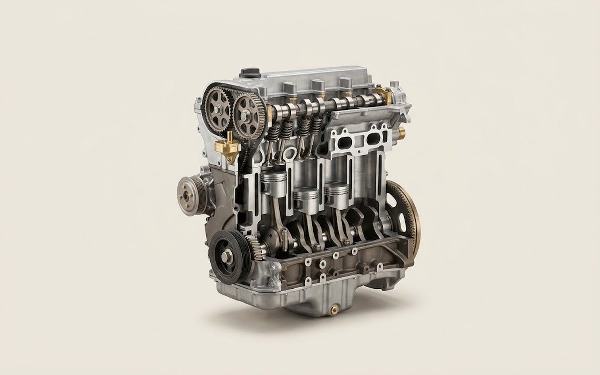 How it works · 3D
How a Car Engine Works
How the part you're working on actually works — in plain English, on a 3D model.
Open in 3D →