Autopapyrus · Hummer H2 6.0 V8 (LQ4, 2005)
https://autopapyrus.com/guides/hummer/h2/crankshaft-replacement/
https://autopapyrus.com/guides/hummer/h2/crankshaft-replacement/
Compiled automatically from service literature and owner experience. Specs are for the typical configuration — check them against your exact car before you start.
Hummer H2 6.0 V8 (LQ4, 2005): Crankshaft Replacement
Replacing the crankshaft on a Hummer H2 with the LQ4 6.0 V8 engine is a complex major overhaul procedure. It requires removing the engine completely, disassembling the block and carefully inspecting all related components (bearings, thrust bearings, connecting rods). Reasons for replacement include scored journals, cracks, severe wear and spun bearings. The work is done in a shop setting with lifting equipment. It requires knowledge of torque specifications, the main bearing cap tightening sequence and bearing clearance measurement.
Parts
8- 🔩 GM crankshaft 12552216 (casting 12552216, for LQ4/LQ9 6.0L, 58-tooth reluctor wheel) or equivalent
- 🔩 main bearing set (upper shells with oil groove, lower shells plain; thrust bearings for center journal No. 3)
- 🔩 rod bearing set
- 🔩 M10 main bearing cap bolts (inner and outer, 20 pcs - replacement recommended because they are torque-to-yield fasteners)
- 🔩 M8 cap side bolts (10 pcs, GM recommends replacement)
- 🔩 cylinder head gaskets (for full disassembly)
- 🔩 complete engine gasket set
- 🔩 engine oil and filter
Step by step
53 steps- Remove the hood, disconnect the negative battery terminal, drain the engine oil and coolant, and disconnect the air filter and intake duct.
- Remove the exhaust manifolds, disconnect the oxygen sensors, and remove the exhaust system from the manifold outlets.
- Disconnect the wiring harnesses from the engine control module (ECM) and transmission control module (TCM). Disconnect all sensors (oil pressure, temperature, crankshaft position, camshaft position). Remove the alternator and starter. Move the A/C compressor aside and secure it to the frame without disconnecting the lines.
- Remove the drive belt. Remove the crankshaft damper (the damper bolt is tightened to 325 N·m (240 lb-ft), so you will need an impact wrench or a holding tool; the new bolt is tightened in two stages: first pass 50 N·m (37 lb-ft), then an additional 140 degrees). Remove the power steering pump and secure it aside.
- Disconnect the fuel lines (relieve the system pressure first), coolant hoses, vacuum lines and the throttle cable (if equipped).
- Raise the vehicle on a lift, remove the engine skid plate, and disconnect the exhaust downpipe from the manifolds.
- Position the lifting beam over the engine and attach chains or straps to the lifting eyes on the block. Remove the bolts securing the engine mounts to the frame (left and right mounts).
- Separate the transmission from the engine (bolts securing the automatic transmission housing to the block, 6-8 bolts, 15-18 mm). Carefully move the transmission rearward (if access allows), or leave the transmission in place and remove the engine forward (disconnect the torque converter from the flexplate through the starter opening by removing the torque converter bolts, 6 bolts, 15 mm).
- Slowly lift the engine with the crane, making sure nothing catches on the frame, wiring or hoses. Bring the engine out of the engine bay toward the front and set it on an engine stand or pallet.
- On the stand, remove the intake manifold (10 mm bolts, reassembly torque 12 N·m (106 lb-in)), the valve covers (10 mm bolts, torque 12 N·m (106 lb-in)), and the oil pan (10 mm bolts, reassembly torque 25 N·m (18 lb-ft)).
- Remove the bolts securing the oil pickup tube to the oil pump (10 mm bolt) and to the bracket on the main bearing cap (13 mm nut). Remove the oil pickup tube.
- Remove the windage tray (crankshaft baffle) by removing the nuts securing it to the main bearing cap studs (10 mm).
- Remove the six bolts securing the flywheel (flexplate) to the crankshaft flange (15 mm, reassembly torque 100 N·m (74 lb-ft)), using a holding tool. Remove the flywheel (if it sticks, tap lightly around the perimeter with a plastic mallet).
- Remove the crankshaft position (CKP) sensor from the rear passenger side of the block (sensor mounting bolt). Gently pry the sensor out, taking care not to damage the reluctor ring on the crankshaft.
- Inspect the main bearing caps. They are stamped with numbers 1-5 (front to rear) and directional arrows (the cap "wings" should face rearward, except for cap No. 5). If there are no markings, mark each cap's number and installation direction with a center punch or marker.
- Remove the main bearing cap side bolts (two M8 bolts per cap, 10 total; 10 mm socket; GM recommends replacing the bolts at reassembly and applying sealant to the threads).
- Remove the main bearing cap bolts (four M10 bolts per cap, 20 total: the outer bolts have a 15 mm deep head, the inner bolts 13 mm; some bolts are stud-type for accessories). Loosen the bolts in the reverse of the tightening sequence (outer bolts first, then inner).
- Remove the main bearing caps (lift straight up without tilting; if a cap is stuck, tap lightly with a plastic mallet through a wooden block). Lay the caps out in order with their bolts.
- Carefully lift the crankshaft out of the engine block, holding it by the front journal (snout) and the rear flange. Lift straight up, avoiding hitting the journals against the block walls. Wear non-slip protective gloves (the LQ4 crankshaft weighs about 25 kg (55 lb)).
- Place the crankshaft in V-blocks or a protective crate to prevent bending and journal damage.
- Remove the main bearing shells from the block (upper, with oil groove) and from the caps (lower, plain). Label each shell by journal number for inspection.
- Remove the thrust bearings (half-rings) from center journal No. 3 (located on both sides of the main journal in the block and the cap).
- Inspect the bearing seats in the block and caps for scoring, cracks and distortion. Clean with solvent and dry with compressed air.
- Inspect the old crankshaft with a micrometer: measure the main and rod journal diameters (nominal main journal diameter 69.871-69.889 mm; for rod journals, check the service manual). Out-of-round and taper must not exceed 0.005 mm. If exceeded, regrind to an undersize or replace the crankshaft.
- Check the crankshaft end play (controlled by the thrust bearings on journal No. 3): nominal end play 0.06-0.19 mm. If exceeded, replace the thrust bearings.
- Install the new main bearing shells in the block (upper, with groove) and in the caps (lower, without groove). Each shell has a locating tab that fits into a notch in the block or cap. Check that the shell is fully seated and flush with the block surface.
- Install the new thrust bearings on center journal No. 3 (in the block and in the cap), lubricated with engine oil on both sides. Be sure to lubricate the working surfaces of the thrust washers with oil or assembly lube.
- Generously lubricate all main bearing shells in the block with engine oil or assembly lube, paying special attention to the thrust surfaces of the No. 3 shells.
- Lubricate the main journals of the new (or reground) crankshaft with engine oil.
- Slowly lower the crankshaft into the block, aligning the journals with the bearing shells. You may need to tilt the crankshaft slightly to clear the block openings. Avoid scratches and impacts.
- Lubricate the lower bearing shells in the main bearing caps with engine oil.
- Install the main bearing caps strictly according to number and direction (cap wings face rearward, except cap No. 5). Insert the M10 bolts (the longer bolts without studs go toward the center, the stud-type bolts go to the outside) and snug the caps by hand, alternating between bolts for even seating.
- Tighten the inner M10 main bearing cap bolts (13 mm heads, numbered 1-10 in the tightening sequence diagram): first pass 20 N·m (15 lb-ft), in a sequence from the center outward (usually No. 3, then No. 2, No. 4, No. 1, No. 5, but see the service manual for the exact sequence).
- After the first pass on the inner bolts, tap the crankshaft rearward (toward the flywheel) with a plastic mallet, then forward (toward the snout) to align the thrust bearings.
- Tighten the inner M10 bolts with the second pass: an additional 80 degrees using a torque angle gauge, in the same sequence.
- Tighten the outer M10 main bearing cap bolts (15 mm heads, numbered 11-20): first pass 20 N·m (15 lb-ft) in sequence, then an additional 51 degrees.
- Tighten the M8 side bolts of the main bearing caps to 24 N·m (18 lb-ft) (no angle tightening). Before installing, apply a thin layer of anaerobic sealant to the threads of the side bolts (GM recommends sealant to prevent oil leaking through the threads into the block passages).
- Check that the crankshaft turns freely by hand (it should rotate without binding). If it binds, check that the caps are installed correctly, the tightening torque, and the bearing clearances (the bearing size may be wrong or the bolts overtightened).
- Measure the crankshaft end play with a dial indicator or feeler gauge (push the crankshaft back and forth with a pry bar against the front end; end play 0.06-0.19 mm).
- Install the windage tray on the main bearing cap studs and tighten the nuts to 24 N·m (18 lb-ft).
- Install the oil pickup tube: tighten the bolt securing it to the pump to 12 N·m (106 lb-in) and the nut securing it to the cap bracket to 24 N·m (18 lb-ft).
- Install the oil pan with a new gasket (or sealant, depending on the version) and tighten the oil pan bolts to 25 N·m (18 lb-ft).
- Install the flywheel (flexplate) on the crankshaft flange, aligning the holes. Tighten the six bolts to 100 N·m (74 lb-ft) in a crisscross sequence (using a flywheel holding tool).
- Install the crankshaft position sensor in the rear of the block and tighten the mounting bolt to 12 N·m (106 lb-in). Check the clearance between the sensor and the reluctor ring (0.5-1.5 mm, set automatically when the sensor is seated).
- Install the intake manifold, valve covers and accessories (alternator, starter, A/C compressor, power steering pump) in the reverse order of removal.
- Install the engine in the Hummer H2 engine bay using the crane: lower the engine into the opening, align the engine mounts with the frame brackets, and tighten the mount bolts to 50-70 N·m (37-52 lb-ft) (exact value per the chassis service manual).
- Connect the transmission to the engine: seat the torque converter in the flexplate, tighten the transmission-to-block bolts to 50 N·m (37 lb-ft), and the torque converter-to-flexplate bolts to 65 N·m (48 lb-ft).
- Connect all electrical connectors (ECM, TCM, sensors, starter, alternator), fuel lines, coolant hoses and vacuum lines.
- Install the exhaust manifolds, oxygen sensors and exhaust downpipe. Install the crankshaft damper (new bolt: first pass 50 N·m (37 lb-ft), then an additional 140 degrees).
- Install the drive belt, fill the cooling system with coolant, add engine oil (LQ4 capacity with filter is 6 L (6.3 qt)), and install a new oil filter.
- Connect the battery, visually inspect for leaks, and start the engine. Within the first 10-15 seconds of running, the oil pressure warning light should go out (if it does not, shut the engine off immediately and check the lubrication system).
- Warm the engine to operating temperature at idle and check for oil, coolant and fuel leaks. Listen for unusual noises (knocking from the lower part of the block indicates incorrect assembly or insufficient lubrication).
- Break in the engine: for the first 500 km (300 miles), avoid hard acceleration and engine speeds above 3500 rpm. Change the oil and filter after 500-1000 km (300-600 miles) to remove break-in debris.
Common mistakes and warnings
- Replacing the crankshaft is a major engine overhaul that requires experience working with internal combustion engines, special tools (torque wrench, angle gauge, micrometer) and a shop environment. Incorrect main bearing cap tightening (too loose or too tight), failing to lubricate the bearings during assembly, mixing up the caps or installing the thrust bearings incorrectly will lead to engine seizure, spun bearings or a broken crankshaft within the first minutes of operation. Main bearing cap bolts are torque-to-yield (single-use), and reusing old bolts without replacing them may cause them to stretch and loosen the cap clamping force. If you have no experience building engines, leave the work to an engine machine shop. When installing a new crankshaft, be sure to measure the bearing clearances using Plastigage or a micrometer (nominal main bearing clearance 0.038-0.051 mm; the exact value depends on the bearing and crankshaft size grades). Failing to meet the clearances will lead to oil starvation or bearing damage. Break-in after an engine overhaul is mandatory: during the first 500 km the bearings, piston rings and other friction pairs seat in, and skipping the break-in will shorten engine life.
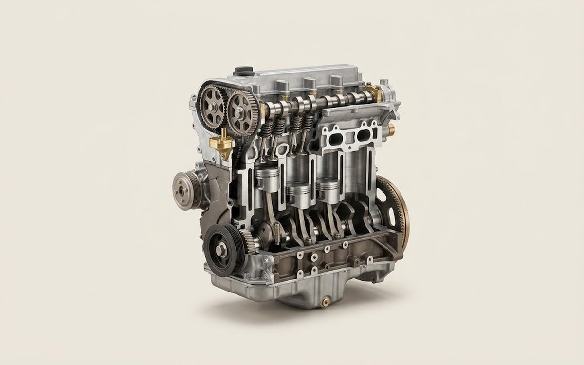 How it works · 3D
How a Car Engine Works
How the part you're working on actually works — in plain English, on a 3D model.
Open in 3D →