Autopapyrus · Mazda Mazda6 2.5 SKYACTIV-G PY-VPS (2012)
https://autopapyrus.com/guides/mazda/mazda6/engine-overhaul/
https://autopapyrus.com/guides/mazda/mazda6/engine-overhaul/
Compiled automatically from service literature and owner experience. Specs are for the typical configuration — check them against your exact car before you start.
Mazda Mazda6 2.5 SKYACTIV-G PY-VPS (2012): Engine Overhaul
An overhaul of the 2.5 SKYACTIV-G PY-VPS engine includes full disassembly, inspection of the block and cylinder head, cylinder boring (or sleeving, since the block has thin aluminum-alloy walls with molybdenum-coated bores 4340, which limits boring options; with significant wear, sleeves are installed), replacement of the piston assembly, main and rod bearings and valve stem seals, and reassembly with precise clearances and torque specs. The work requires access to machine shop equipment (boring machine, honing machine, pressure-testing stand) and experience assembling high-output engines.
Parts
5- 🔩 Piston assembly: pistons, rings, pins, retaining clips
- 🔩 main and rod bearing shells (standard or undersize)
- 🔩 valve stem seals
- 🔩 gasket and seal kit (head gasket, oil pan gasket, crankshaft seals)
- 🔩 as needed: complete crankshaft, camshafts, hydraulic lash adjusters. Exact OE numbers depend on the repair size, so confirm them after inspection
Step by step
16 steps- Remove the engine from the car: disconnect the battery, drain the engine oil (sump capacity about 4.3 L (4.5 qt)), the coolant and the fuel from the system. Disconnect all accessories (alternator, A/C compressor, starter), the exhaust system, fuel lines, wiring and hoses. Unbolt the engine mounts and lift the powertrain out with a hoist. It is easier to remove the engine together with the transmission, then separate them on a stand.
- External cleaning and accessory removal: clean the engine of dirt and oil deposits with a pressure washer or degreaser. Remove the intake and exhaust manifolds, the accessory drive belt cover, the alternator, the water pump, the oil filter and the oil cooler.
- Remove the cylinder head: remove the valve cover, the timing chain (automatic tensioner and guides) and the camshafts. Loosen the cylinder head bolts in the reverse of the tightening sequence (from the edges to the center, diagonally). Remove the head, noting its position. Check the head surface for flatness (maximum 0.05 mm over a length of 200 mm; if exceeded, resurfacing is required).
- Disassemble the cylinder block: turn the block over, remove the oil pan, the oil pickup and the balance shafts (dual-shaft balancer with a gear drive from the crankshaft). Mark the main bearing caps and connecting rod caps (each must go back in its original place and orientation). Remove the connecting rod bolts (assembly torque 48-50 N·m (35-37 lb-ft)) and the main cap bolts (torque 54-58 N·m (40-43 lb-ft)). Remove the crankshaft (use special tool SST 49 E011 1A0 or soft pads to avoid damaging the journals). Remove the pistons with the connecting rods through the top of the block, after first removing the piston pin retaining clips.
- Inspect the block and crankshaft: measure the cylinder diameter with a bore gauge at three heights and in two directions (standard diameter 89.0 mm). Allowable out-of-round and taper: up to 0.01 mm; if exceeded, boring or sleeving is required. Note: the SKYACTIV-G block has thin walls (optimized for the high 13.0:1 compression ratio), so boring is possible by no more than 0.25-0.50 mm (confirm with the machinist after measuring wall thickness); with greater wear, install cast-iron sleeves. Measure the crankshaft journals with a micrometer (main journals diameter 49.98-50.00 mm, rod journals standard size). If wear exceeds 0.03 mm, regrind the crankshaft to an undersize (bearings of -0.25 mm are usually available).
- Boring and honing the block: take the block to a machine shop. Boring is done to the size of the new pistons (standard or oversize +0.25/+0.50 mm; check availability with your Mazda parts supplier). After boring, final honing with a 45-60° crosshatch angle is mandatory for proper ring break-in. Piston-to-cylinder clearance after machining should be 0.025-0.045 mm (maximum allowable 0.066 mm). Wash the block with hot water and detergent, blow out the oil passages with compressed air, and dry it.
- Prepare the piston assembly: install the piston rings on the new pistons. Check the ring end gap by inserting the ring into the cylinder and squaring it with a piston: compression ring gap is usually 0.20-0.35 mm, oil ring 0.25-0.50 mm (exact values for the PY-VPS are not published in open sources, so follow the ring manufacturer's instructions). When installing the oil ring, make sure the end gaps of the upper and lower rails do not line up (rotate them 180°). The gaps of all rings on one piston must also be spaced 120° apart.
- Assemble the connecting rod and piston assemblies: press the piston pins into the pistons and rods (the pins usually have an interference fit, requiring the piston to be heated to 60-80°C or a special drift). Install the retaining clips in the piston grooves. Lubricate the pistons and rings with clean engine oil.
- Install the bearings and crankshaft: wipe the main bearing seats in the block, install the upper bearing shells (they have an oil groove and hole; the shells with thrust washers go on the center main journal, usually the third of five). Lubricate the shells with engine oil. Lay the crankshaft in the block. Install the lower shells in the caps and lubricate them. Before final tightening, check the clearance with Plastigage: lay a gauging strip on each journal, close the caps at 20 N·m (15 lb-ft), remove the caps and measure the width of the flattened strip (allowable main bearing clearance 0.020-0.055 mm). With correct clearance, tighten the main cap bolts to 54-58 N·m (40-43 lb-ft) (some sources specify multi-stage tightening; check the service manual). Turn the crankshaft by hand; it must rotate without binding.
- Install the pistons in the block: insert the pistons with rods into the cylinders from the top, using a ring compressor (the rings must be compressed flush with the piston skirt). Orient the piston by its mark (usually the arrow on the piston crown should point toward the front of the engine). Tap the piston down with the hammer handle until the rod contacts the crankshaft journal. Install the rod bearing shells (lubricate them with oil), and close the rod caps (do not mix up cylinder numbers and orientation!). Check the clearance with Plastigage (allowable rod bearing clearance 0.026-0.052 mm, maximum 0.10 mm). Tighten the rod bolts to 48-50 N·m (35-37 lb-ft). Repeat for all four cylinders.
- Install the balance shafts and oil pan: assemble the balancer unit (dual-shaft, with a gear drive from the crankshaft, 2:1 ratio), and align the gear marks per the service manual. Lubricate the balancer bearings and install the balancer unit on the cylinder block with a new gasket. Clean the mating surfaces of the oil pan and block of old sealant. Apply a thin layer of anaerobic sealant (or install a new gasket if the design calls for it), install the oil pan and tighten the bolts to 10-12 N·m (89-106 lb-in) in a crisscross pattern.
- Replace the valve stem seals and assemble the cylinder head: remove the old valve stem seals from the valve guides (use a puller or collet tool). Lubricate the new seals with engine oil and carefully press them onto the guides with a drift (do not tilt them, or they will be damaged). Install the valves, springs, retainers and keepers (use a valve spring compressor). Assemble the camshafts with new seals, install the timing chain with a new tensioner and guide, and align the TDC marks.
- Install the cylinder head on the block: clean the block and head surfaces (no traces of old gasket or sealant should remain). Install the new head gasket (it requires no sealant and is installed dry). Carefully lower the head onto the block, aligning the dowel pins. Lubricate the threads and under-head surfaces of the head bolts with engine oil. Tighten the bolts in 4 stages, from the center outward: stage 1: 13-17 N·m (10-13 lb-ft), stage 2: 43-47 N·m (32-35 lb-ft), stage 3: turn an additional 85-95° (use an angle gauge on the torque wrench), stage 4: another 85-95°. Check the final bolt length (standard 99.2-99.8 mm, maximum 100.5 mm; replace the bolts if exceeded).
- Install accessories: install the intake and exhaust manifolds with new gaskets, connect the fuel rail with the injectors (multi-hole nozzles; clean off carbon deposits), install the ignition coils and sensors (MAF, coolant temperature, oil pressure, crankshaft and camshaft position). Install the water pump, alternator, accessory drive belt and oil filter.
- Install the engine in the car: set the engine back onto the subframe or into the engine bay and tighten the mounts. Connect the transmission, exhaust system, all hoses and wiring. Fill with engine oil (4.5 L (4.8 qt) + 0.2 L (0.2 qt) in the filter; use SAE 0W-20 or 5W-30 per the Mazda specification) and coolant. Connect the battery.
- First start and break-in: before starting, crank the engine with the starter (with ignition and fuel disabled) for 10-15 seconds to prime the oil. Start the engine and monitor oil pressure (it should rise within the first 5-10 seconds). Warm it up to operating temperature at idle and check for oil and coolant leaks. For the first 500-1000 km, drive gently without exceeding 3500 rpm and avoid hard loads, to seat the rings and bearings. Change the oil and filter after break-in (the break-in oil collects metal particles).
Common mistakes and warnings
- Overhauling a SKYACTIV-G 2.5 engine is a difficult job that requires professional machine shop equipment (boring machine, honing, crankshaft balancing) and precise measuring tools. The block of this engine has thin aluminum walls with molybdenum-coated bores; boring is limited to 0.25-0.50 mm, and with greater wear sleeving is used (confirm feasibility with the machinist after measurement). Incorrect tightening of the head bolts or main caps will lead to block distortion, leaks or bearing failure. Failing to observe ring and bearing clearances leads to scoring and repeat failure. If you have no experience overhauling modern high-output engines (13.0:1 compression ratio), contact a specialized engine shop.
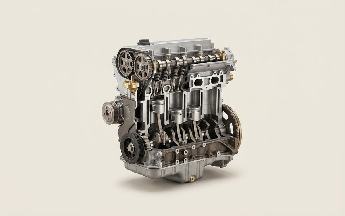 How it works · 3D
How a Car Engine Works
How the part you're working on actually works — in plain English, on a 3D model.
Open in 3D →