Autopapyrus · Mercedes-Benz Sprinter W906 2.2 CDI OM646 (2008)
https://autopapyrus.com/guides/mercedes-benz/sprinter/engine-overhaul/
https://autopapyrus.com/guides/mercedes-benz/sprinter/engine-overhaul/
Compiled automatically from service literature and owner experience. Specs are for the typical configuration — check them against your exact car before you start.
Mercedes-Benz Sprinter W906 2.2 CDI OM646 (2008): Engine Overhaul
An overhaul of the 2.2 L OM646.986 diesel engine involves complete disassembly, inspection of the cylinder block and head, boring the cylinders for oversize pistons, regrinding or replacing the crankshaft, replacing the piston assemblies and plain bearings, and reassembly following the specified torque values and sequence of operations. The OM646 has a cast iron cylinder block (88 mm bore, 88.3 mm piston stroke) and an aluminum 16-valve cylinder head with hydraulic lifters and a chain-driven valvetrain.
Part
- 🔩 piston set with rings and pins (oversize +0.5 or +1.0 mm depending on wear), main and connecting rod bearing shell set (standard or undersize), full engine gasket set, valve stem seals, cylinder head bolts (single-use, must be replaced), connecting rod and main bearing cap bolts (single-use), timing chain with tensioner and guides (if worn), water pump, oil pump (if worn), crankshaft seals (front and rear), reinforced cylinder head gasket, engine oil 10W-40 or 5W-30 (8-10 L (8.5-10.6 qt)), coolant (12-14 L (12.7-14.8 qt)), oil filter and fuel filter. The cost of an overhaul kit varies depending on the parts manufacturer and the degree of wear
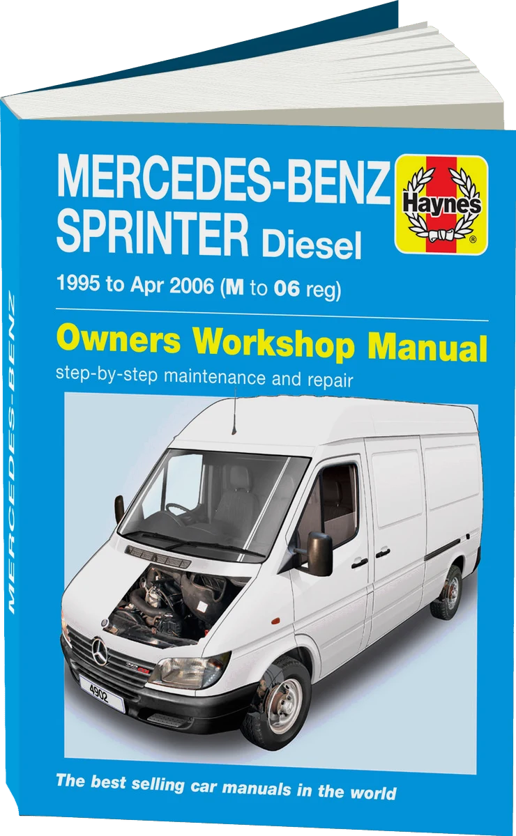 There's a full repair manual for this car
Every system, wiring diagrams and torque specs — not just this job. Haynes and 7 more.
See manuals →
Step by step
17 steps- Remove the engine from the vehicle. Disconnect the battery, drain the oil and coolant, and disconnect all electrical connectors (sensors, injectors, starter, alternator), the high- and low-pressure fuel lines, the cooling system hoses, the exhaust manifold, and the accessory drive belts. Unbolt the engine mounts (tightening torque at assembly 32-47 N·m (24-35 lb-ft)) and lift the powertrain out with a crane or hoist. Mount it on an engine stand for disassembly.
- Remove the accessories. Remove the alternator, starter, A/C compressor (without opening the refrigerant system), high-pressure fuel pump with the fuel injectors, intake and exhaust manifolds (intake manifold tightening torque at assembly 25 N·m (18 lb-ft)), turbocharger (if equipped), water pump, thermostat, oil filter and housing, and oil pan. Mark the position of all components for correct reassembly.
- Remove the cylinder head. Unbolt the valve cover (tightening torque at assembly 7-10 N·m (5-7 lb-ft)), set the timing marks to TDC of cylinder 1, remove the timing chain tensioner, and take the chain off the camshafts. Loosen the cylinder head bolts in the reverse of the tightening sequence (from the outside toward the center), using a hex bit. Remove the head and clean the mating surface of old gasket material. Inspect the head for cracks and check the sealing surface for flatness with a straightedge and feeler gauge (maximum permitted warpage 0.05 mm; if exceeded, the head must be resurfaced).
- Remove the pistons with the connecting rods. Turn the crankshaft so the piston is at BDC, unbolt the connecting rod bearing caps (mark the cylinder number on the cap and the rod), and push the piston and rod out through the top of the cylinder with a wooden hammer handle. Repeat for all four cylinders. Inspect the pistons: scoring, burn-through and cracks require replacement. Measure the piston ring end gaps (specification 0.3-0.5 mm for compression rings, 0.25-0.5 mm for oil control rings).
- Remove the crankshaft. Unbolt the main bearing caps in the reverse of the tightening sequence (from the outside toward the center). Tightening torque at assembly: first pass 55 N·m (41 lb-ft), second pass an additional 90-100 degrees. Lift the crankshaft out of the block. Inspect the crankshaft journals with a micrometer. Wear of more than 0.03 mm requires regrinding to an undersize for the bearing shells (standard sizes -0.25, -0.50, -0.75, -1.00 mm). Check the crankshaft runout on V-blocks (tolerance up to 0.02 mm).
- Inspect the cylinder block. Measure the cylinder diameter with a bore gauge in three zones (top, middle, bottom) and in two directions (along and across the engine axis). Standard cylinder diameter is 88.00 mm, permitted wear up to 0.15 mm. If out-of-round or taper exceeds 0.03 mm, boring is required. Oversize piston sizes: +0.50 mm and +1.00 mm (diameters 88.50 and 89.00 mm). Check the block deck surface where it mates with the head using a straightedge. Warpage of more than 0.05 mm requires resurfacing.
- Bore the cylinders on a machine. Boring is done to the first oversize (+0.50 mm) if wear allows, or to +1.00 mm if wear is severe. After boring, hone the cylinders to create the correct crosshatch pattern on the walls (angle 45-60 degrees). Wash the block with hot water and detergent, blow it dry with compressed air, and wipe it with a rag soaked in engine oil to prevent corrosion.
- Regrind or replace the crankshaft. If the crankshaft journals are worn, regrind them on a specialized machine to the undersize for the bearing shells. The grinding must produce a surface roughness of Ra 0.2-0.4 µm and geometry within a tolerance of 0.005 mm. After grinding, wash the crankshaft and blow out the oil passages with compressed air. If the journals are worn by more than 1.00 mm or there are cracks, the crankshaft must be replaced.
- Assemble the short block. Install the main bearing shells in the block and caps (lubricate with engine oil), lay in the crankshaft, install the main bearing caps (observing the markings and orientation), and tighten the bolts with a torque wrench: first pass 55 N·m (41 lb-ft), second pass an additional 90-100 degrees. Check that the crankshaft turns freely by hand. Install new crankshaft seals (front and rear) using a seal driver.
- Install the pistons on the connecting rods. Press the piston pins into the pistons and rods (at room temperature or with the piston heated to 60-80 degrees), and install the pin retaining clips. Fit the piston rings onto the pistons with a ring installation tool, starting with the oil control ring (bottom), then the two compression rings. Check the ring end gaps with a feeler gauge (specification 0.3-0.5 mm). Stagger the ring gaps at 120 degrees to each other.
- Install the pistons with the connecting rods into the block. Lubricate the cylinder walls with engine oil, compress the piston rings with a ring compressor, and insert the piston into the cylinder (the arrow on the piston crown points toward the front of the engine). Install the connecting rod bearing shells in the rod and cap, fit the cap onto the rod (aligning the cylinder number marks), and tighten the connecting rod bolts with a torque wrench: first pass 42 N·m (31 lb-ft), second pass an additional 90 degrees (connecting rod bolts are single-use and must be replaced). Repeat for all pistons. Turn the crankshaft by hand. It should rotate smoothly without binding.
- Assemble the cylinder head. Replace the valve stem seals (using a seal installer and valve spring compressor), lap or replace the valves (if there are signs of burning or seat wear), and check the hydraulic lifters for sticking (they should compress only with effort). Clean all passages in the head and dry them with compressed air. Check the camshafts for wear on the lobes and journals (wear of more than 0.05 mm requires replacement).
- Install the cylinder head on the block. Lay the new head gasket (without sealant, since the gasket already has an elastomer coating), aligning it on the dowel sleeves. Carefully lower the head onto the block without shifting the gasket. Lubricate the threads and under-head surfaces of the new head bolts with engine oil. Tighten the head bolts with a torque wrench from the center outward in four stages: first pass 15 N·m (11 lb-ft), second pass 35 N·m (26 lb-ft), third pass an additional 90 degrees, wait 10 minutes, fourth pass an additional 90 degrees. Head bolts are single-use and must never be reused.
- Install the timing chain and camshaft drive. Install the camshafts in the head (lubricate the journals with oil), install the camshaft sprockets, and fit the timing chain, aligning the marks on the crankshaft and camshaft sprockets according to the TDC marks for cylinder 1. Install the chain tensioner and guides. Turn the crankshaft two full revolutions and check that the marks line up. Install the valve cover with a new gasket (tightening torque 7-10 N·m (5-7 lb-ft)).
- Install the accessories and cooling system components. Install a new water pump (mounting bolt torque 10-15 N·m (7-11 lb-ft)), the thermostat, intake manifold (torque 25 N·m (18 lb-ft)), exhaust manifold (torque 25 N·m (18 lb-ft)), turbocharger (if equipped), high-pressure fuel pump (torque 25 N·m (18 lb-ft)), injectors, alternator, starter, A/C compressor, and the accessory belt tensioner and belt. Install the oil pan with a new gasket or sealant (bolt torque 10-15 N·m (7-11 lb-ft)) and a new oil filter.
- Install the engine in the vehicle. Secure the powertrain on the mounts (torque 32-47 N·m (24-35 lb-ft)), connect all electrical connectors (sensors, injectors, starter, alternator), the fuel lines (torque 10-20 N·m (7-15 lb-ft) for fuel lines), the cooling system hoses, and the exhaust system. Fill with engine oil (8-10 L (8.5-10.6 qt) depending on the equipment), fill with coolant (12-14 L (12.7-14.8 qt)), and bleed the cooling system to remove air pockets.
- Perform the first start and break-in. Before starting, crank the engine with the starter for 5-10 seconds without fuel delivery (disable the injectors or the fuel pump relay) to circulate oil through the system. Start the engine and warm it up to operating temperature at idle (monitor the oil pressure, which should be 2-4 bar (29-58 psi) at idle), and check for oil, coolant and fuel leaks. For the first 1,000-1,500 km, drive gently without heavy loads or high revs (up to 3,000 rpm) and avoid hard acceleration. Change the oil and filter after the first 1,000 km of break-in.
Common mistakes and warnings
- An engine overhaul requires a high skill level, specialized tools and strict adherence to the procedure. Incorrect tightening of the cylinder head bolts or main bearing bolts will lead to engine destruction. Cylinder boring and crankshaft grinding must be done only on specialized machines. Working on them with a file or a drill is unacceptable. Cylinder head bolts, connecting rod bolts and main bearing bolts are single-use, and the manufacturer prohibits reusing them (plastic deformation occurs with angle tightening). If you have no overhaul experience, take the engine to a specialized engine machine shop, because assembly mistakes cost more than the labor.
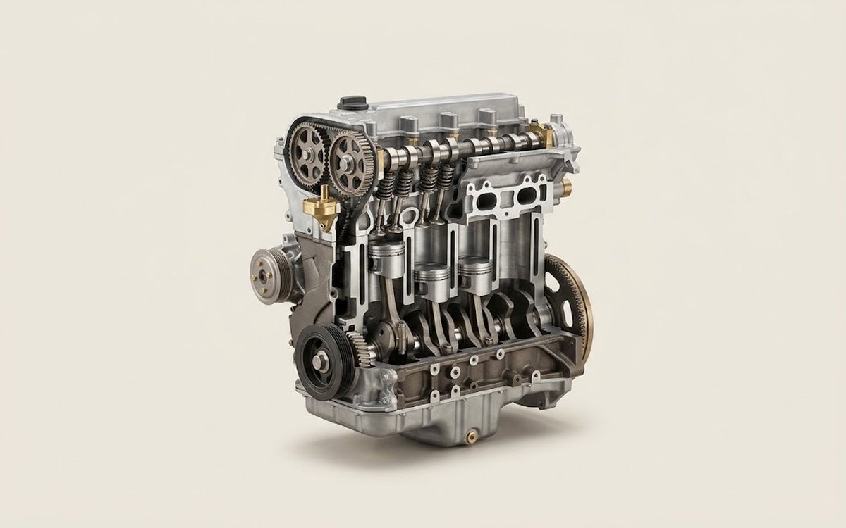 How it works · 3D
How a Car Engine Works
How the part you're working on actually works — in plain English, on a 3D model.
Open in 3D →