Autopapyrus · Nissan Skyline R34 GT-R RB26DETT (2000)
https://autopapyrus.com/guides/nissan/skyline/engine-overhaul/
https://autopapyrus.com/guides/nissan/skyline/engine-overhaul/
Compiled automatically from service literature and owner experience. Specs are for the typical configuration — check them against your exact car before you start.
Nissan Skyline R34 GT-R RB26DETT (2000): Engine Overhaul
An RB26DETT overhaul is a full teardown, inspection, replacement of worn parts and reassembly of the engine. Signs you need one: low compression, oil consumption above 1 L (1.06 qt) per 1,000 km, knocking from the bottom end, or a leak-down test result below 90%. The RB26 is known for its strong block and heads. Past 150,000-200,000 km, or after running increased power, the pistons, bearings and seals will need renewing. The job requires exact torque values and tightening sequences, especially for the head bolts and rod bolts.
Part
- 🔩 piston ring set, main and rod bearing shells (Nissan N1 or equivalents such as ACL Race Series), full engine gasket set, crankshaft seals (front and rear), valve stem seals, cylinder head bolts (single-use, replacement recommended), connecting rod bolts (single-use if you are reusing the stock rods), oil pump gasket, water pump, timing belt and tensioner, camshaft seals. As needed: pistons (CP Pistons, Wiseco, JE), uprated connecting rods (Spool H-beam, Manley), oversize bearing shells, ARP head studs (for planned power above 400 hp)
Step by step
16 steps- Remove the engine from the car. Drain all fluids (oil, coolant, fuel from the fuel rail). Disconnect the wiring (injector, ignition coil and sensor connectors). Remove the turbochargers, the intake and exhaust manifolds and the accessories (alternator, starter, A/C compressor). Hoist the engine with a crane and unbolt the engine mounts. The engine with accessories weighs about 250 kg (550 lb), so you need at least two people.
- Disassemble the ancillaries and top end. Remove the timing belt (use the marks on the camshaft and crankshaft pulleys), the camshaft pulleys, the valve covers and the cylinder heads. Loosen the head bolts in the reverse of the tightening sequence, from the outside toward the center, 1/4 turn per pass. The head bolts are single-use, so do not reuse them.
- Remove the pistons and rods. Turn the block over. Remove the oil pan (M6 bolts: 6-8 N·m (4-6 lb-ft), M10 bolts: 30-40 N·m (22-30 lb-ft)), the oil pickup and the rod caps (loosen evenly, in a diagonal pattern). Mark each rod and cap with its cylinder number using a marker or a center punch. Push the pistons and rods out through the top of the block without damaging the cylinder walls.
- Remove the crankshaft. Undo the main bearing cap bolts (loosening torque 46-52 N·m (34-38 lb-ft), sequence from the outside toward the center) and lift out the crankshaft. Do not mix up the upper and lower bearing shells. Each one has a locating tab in a specific position. Check crankshaft runout with a dial indicator, on V-blocks or in the block. Allowable runout is no more than 0.03 mm (a new crankshaft is 0.01-0.02 mm). If runout is above 0.05 mm, straighten or replace the crankshaft.
- Inspect the parts. Check the cylinders for scoring. Measure the bore diameter at three levels (top, middle, bottom) and in two directions (along and across the crankshaft axis). Allowable out-of-round and taper are up to 0.05 mm. If wear is greater, bore the block to an oversize of +0.25/+0.50/+0.75 mm and fit oversize pistons. Measure the crankshaft journals with a micrometer (main journals nominal 60 mm, rod journals 52 mm, tolerance within 0.01 mm). If wear exceeds 0.03 mm, regrind to an undersize. Check the connecting rods for twist and bend on a rod alignment fixture (tolerance 0.05 mm per 100 mm of length). Check the pistons for cracks and skirt scoring, and the rings for sticking and worn end gaps.
- Machine the block and heads. Hone the cylinders (create a cross-hatch for the new rings, angle 45-60 degrees, surface roughness Ra 0.4-0.8 µm). Pressure-test the block and heads for leaks (3-4 bar). Check the head deck flatness on a surface plate (tolerance 0.05 mm, resurface if exceeded). Lap or replace the valves (check sealing with kerosene), and replace the valve guides and valve stem seals. Clean up the coolant passages on the intake side of the heads, where the casting leaves restrictions. Three large passages are often narrowed from the factory, so open them up to the diameter of the adjacent passages for better coolant circulation.
- Determine the bearing clearances. Install the new main bearing shells in the block and caps dry, without lubricant. Lay in the crankshaft and run a strip of Plastigauge across the full width of each journal. Install the caps and tighten the bolts to 46-52 N·m (34-38 lb-ft) (without the angle turn). Remove the caps without rotating the crankshaft and measure the width of the flattened strip against the scale on the package. Nominal main bearing clearance is 0.028-0.047 mm, with a maximum allowable of 0.090 mm. For built engines, the target clearance is 0.04-0.06 mm (extra clearance improves oil supply at high rpm). Repeat the procedure for the rod bearings. Nominal rod bearing clearance is 0.023-0.043 mm, with a maximum of 0.080 mm. Important: the lower shell (in the rod cap) never has an oil groove. The groove is only on the upper shell in the rod body. Otherwise the load distribution will be wrong.
- Install the piston rings. Check the end gap of each ring by placing the ring in the cylinder at a depth of 20 mm and squaring it with a piston. Nominal end gap is 0.20-0.40 mm for the compression rings and 0.15-0.50 mm for the oil rings. A gap that is too small (under 0.15 mm) will cause the ring ends to butt and seize when hot. One that is too large (over 0.80 mm) will cause blow-by and oil consumption. Fit the rings onto the pistons with a ring expander, following the "TOP" marking. Stagger the ring end gaps 120 degrees apart.
- Assemble the bottom end. Lubricate the bearing shells and crankshaft journals with engine oil, lay the crankshaft in the block and install the thrust washers on both sides of the center main bearing. Check crankshaft end play: 0.05-0.18 mm, target 0.10 mm. Center the crankshaft by lightly tapping the nose and the flywheel flange with a plastic mallet so the thrust washers seat evenly all the way around (360 degrees). Install the main bearing caps (observing the numbers and arrow direction) and tighten the bolts to 46-52 N·m (34-38 lb-ft) in a crisscross pattern from the center outward. Turn the crankshaft by hand. It should rotate freely without binding.
- Install the pistons and rods. Lubricate the cylinders with oil and fit a ring compressor. Insert the piston into the cylinder with the arrow on the piston crown facing the front of the engine, and tap it in with the handle of a hammer against the piston crown. Fit the rod cap with its bearing shell and tighten the rod bolts to 14-16 N·m (10-12 lb-ft), then turn a further 60-65 degrees (use an angle gauge). For uprated rods with ARP2000 bolts (3/8 in diameter), the tightening torque is about 75 N·m (55 lb-ft) using ARP Ultra-Torque lubricant. Rod bolts are single-use when running original parts, so do not reuse them.
- Install the oil pump. Use a new gasket (not sealant, because silicone particles can get into the oil system and damage the bearings). Apply medium-strength thread locker to the pump cover bolts. Install the relief valve springs with the adjusting shims (the shims prevent galling of the aluminum housing), and tighten the cover with a new sealing washer. Install the front crankshaft seal with a driver, flush with the face of the block.
- Assemble the cylinder heads. Install the intake and exhaust camshafts (marked on the ends) and the camshaft caps (numbered on each cap). Tighten the cap bolts to 9-12 N·m (7-9 lb-ft) from the center outward in two passes. Check camshaft end play (0.05-0.15 mm) and radial clearance in the journals (0.03-0.08 mm). Install new valve stem seals with a driver (do not strike the valve guides directly).
- Install the heads on the block. Clean the mating surfaces of any old gasket residue and lay down the new head gaskets (multi-layer steel, with the "TOP" or "FRONT" marking toward the front of the engine). Fit the heads, insert new head bolts and tighten in four stages: first pass 30 N·m (22 lb-ft), second pass 108 N·m (80 lb-ft), then loosen ALL bolts completely, third pass 30 N·m (22 lb-ft), fourth pass 103-113 N·m (76-83 lb-ft). The tightening sequence is a spiral from the center outward (see the diagram in the service manual). The small M6 bolts around the perimeter of the combustion chambers are tightened to 6-8 N·m (4-6 lb-ft).
- Install the timing system. Install the crankshaft pulley and tighten the center bolt to 445-465 N·m (328-343 lb-ft) (this requires locking the flywheel or using an impact wrench). Install the camshaft pulleys (14-19 N·m (10-14 lb-ft)). Set the marks: the notch on the crankshaft pulley against the mark on the cover, and the marks on the camshaft pulleys against the marks on the rear timing cover. Fit a new timing belt, install the tensioner and idler pulley (43-58 N·m (32-43 lb-ft)) and tension the belt by turning the tensioner. Turn the crankshaft two full revolutions and check that the marks line up.
- Final assembly. Install the intake and exhaust manifolds, the turbochargers (new gaskets and studs, turbo nut torque 25-35 N·m (18-26 lb-ft)), the fuel rail with injectors, and the accessories (alternator, starter, A/C compressor, power steering pump). Fit the valve covers (bolt torque 2-4 N·m (1.5-3 lb-ft), do not overtighten because the aluminum covers deform easily), and connect all sensors and wiring. Fill with fresh engine oil (5W-40 or 10W-40 synthetic, capacity with filter 5.2 L (5.5 qt)), fit a new oil filter, and fill with coolant (9-10 L (9.5-10.6 qt) for the system).
- Break-in after assembly. Start the engine for the first time with no load and warm it up to 80-90°C (176-194°F). Monitor oil pressure (at least 1 kgf/cm² at idle and at least 3-4 kgf/cm² at 3,000 rpm). For the first 500 km, follow break-in rules: keep revs below 4,000 rpm, keep load under 50% of maximum, and avoid hard acceleration and heavy engine braking. Change the oil after the first 500 km (to flush out break-in debris), then every 3,000-5,000 km. The rings and bearings are fully bedded in by 3,000-5,000 km.
Common mistakes and warnings
- The RB26DETT demands very precise assembly. Mistakes in head bolt or rod bolt tightening lead to a blown head gasket or a broken connecting rod. Always use a torque wrench and an angle gauge for torque-plus-angle bolts. If you have no engine rebuilding experience, take the job to an engine machine shop familiar with the RB series. Do not polish the intake and exhaust ports of the heads to a mirror finish. A polished surface disrupts the boundary layer of the air-fuel mixture and reduces cylinder filling. Do not use silicone sealant on the oil pump gasket. Use only a paper or fiber gasket, or silicone particles will get into the lubrication system. For planned power above 400-450 hp, replace the stock head bolts with ARP studs and upgrade the rotating assembly (forged CP/Wiseco pistons, H-beam Spool/Manley rods).
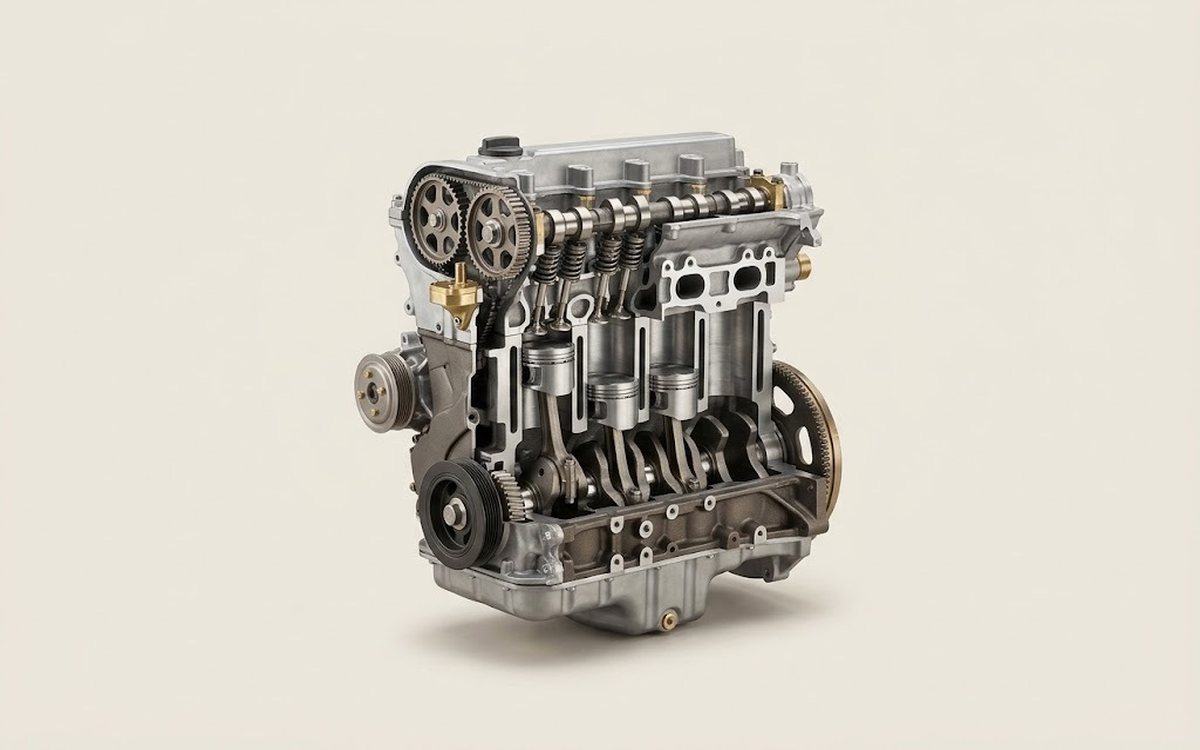 How it works · 3D
How a Car Engine Works
How the part you're working on actually works — in plain English, on a 3D model.
Open in 3D →