Autopapyrus · Opel Frontera A 2.2 (C22SE, 1994)
https://autopapyrus.com/guides/opel/frontera/diagnosing-the-engine-management-system/
https://autopapyrus.com/guides/opel/frontera/diagnosing-the-engine-management-system/
Compiled automatically from service literature and owner experience. Specs are for the typical configuration — check them against your exact car before you start.
Opel Frontera A 2.2 (C22SE, 1994): Diagnosing the Engine Management System
On the Frontera A with the 2.2 engine, fuel injection and ignition are run by a control unit with self-diagnostics, and fault codes are read through the diagnostic connector. Start diagnosis with the mechanical condition and the power supply, not by replacing sensors. A 1994 vehicle does not use the OBD-II standard, so the codes and protocol depend on the specific trim and market. If the scan tool cannot connect, read the codes from the blinking lamp, if your control unit supports that function. Check the exact code table against the manufacturer's service manual for your version.
Part
- 🔩 Depends on the diagnostic results. Typical candidates: oxygen sensor (lambda sensor), coolant temperature sensor, throttle position sensor, idle air control valve, crankshaft position sensor, fuel injector (or injector assembly), fuel pump relay, fuel filter
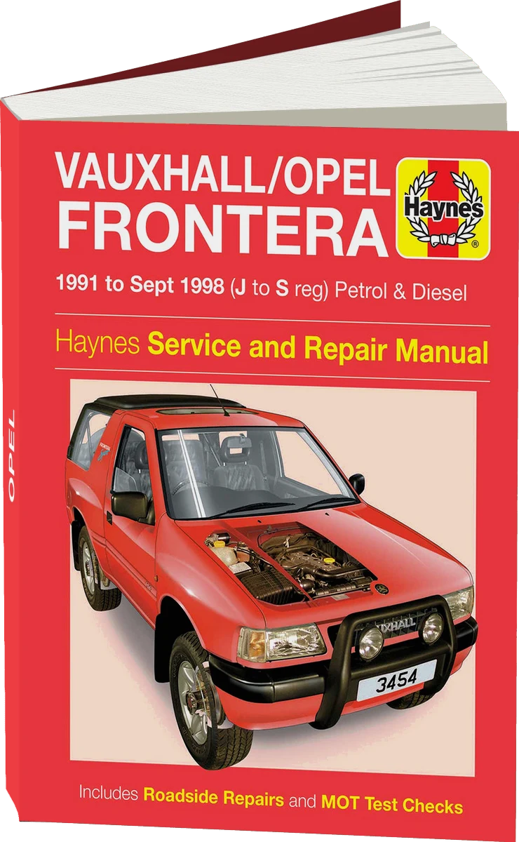 There's a full repair manual for this car
Every system, wiring diagrams and torque specs — not just this job. Haynes and 1 more.
See manuals →
Step by step
12 steps- Preliminary inspection. Check the engine oil and coolant levels, the condition of the air filter, and the tightness of the intake hose clamp behind the airflow meter or throttle body. An air leak at the intake boot causes a fluctuating idle and false fault codes.
- Battery and ground check. Battery voltage with the engine off should be about 12.4-12.7 V, and 13.8-14.4 V with the engine running. Clean and tighten the battery terminals and the ground wires on the body and on the engine block. A weak ground is a common cause of intermittent faults on vehicles of this age.
- Fuse and relay boxes. Inspect the fuses and the relays for the control unit power supply and the fuel pump. Look for corrosion and signs of overheating on the sockets.
- Connecting the scan tool. Find the diagnostic connector in the cabin (usually near the instrument panel or the center console, to the left of the driver) and connect a scan tool with the correct protocol. Select the Opel make and the engine management system. If the connector is not the standard 16-pin type, you will need an adapter.
- Reading the codes. Write down all fault codes, then look at the live data: coolant temperature, oxygen sensor voltage, throttle position, engine speed, and fuel trim. Only after that, clear the codes and check which ones return.
- Checking the coolant temperature sensor. Unplug the connector and measure the sensor resistance with a multimeter. It should drop smoothly as the engine warms up: a few kΩ on a cold engine and less than 1 kΩ on a hot one. Readings that do not match the specification mean the sensor needs replacing. Check the connector wiring for an open or short circuit with a continuity test all the way to the control unit.
- Checking the throttle position sensor. Connect the multimeter to the signal wire and slowly open the throttle. The voltage should rise smoothly, without dropouts or jumps. Dropouts mean the sensor track is worn.
- Checking the oxygen sensor. On a warmed-up engine, the signal should switch quickly in a range of about 0.1-0.9 V. A sluggish or "stuck" signal means either an aging sensor or a rich or lean mixture caused by something else. First rule out air leaks and fuel problems.
- Checking the fuel system. Connect the pressure gauge and compare the pressure with the specification for your injection version. Check the operation of the relay and pump and the condition of the fuel filter. A pressure drop under load points to the pump, the filter, or the pressure regulator.
- Checking the ignition system. Inspect the ignition coil (or coils), the spark plug wires, and the spark plugs. Measure the resistance of the wires; it should not be much higher than the others. Check the crankshaft position sensor and its connector, and inspect the air gap and the condition of the reluctor ring (toothed wheel).
- Checking the idle speed. Inspect the idle air control valve or throttle plate and clean off carbon deposits with a throttle body cleaner. Check the vacuum hoses with a vacuum gauge or by listening for leaks. These are the most common causes of unstable idle.
- Final check. Clear the codes, warm up the engine, and drive for 10-15 minutes under various loads. Read the codes and data again. If a fault returns, check the circuit of that specific sensor: its power supply, ground, signal wire, and connector.
Common mistakes and warnings
- Do not disconnect the battery or unplug the control unit connectors with the ignition on. Do not clear codes without writing them down first, or you will lose that information. The fuel system is under pressure, so relieve the pressure before disassembly and work away from open flames. If you have no experience with electrical systems and fuel systems, leave the job to a repair shop.