https://autopapyrus.com/guides/skoda/octavia/engine-overhaul/
Skoda Octavia 1.8 T (AGU, 150 hp) 2002: Engine Overhaul
The AGU 1.8 T 150 hp engine from the VAG 1.8T 20V family is one of the group's iconic turbo engines. It was fitted to the Octavia Tour, Audi A4 B5, VW Passat B5 and Golf IV. Typical mileage before an overhaul is 250,000-350,000 km. The main weak points are the oil pump (the stock pump does not provide enough pressure, which leads to oil starvation and destruction of the piston/cylinder group) and the piston rings (sticking, with high oil consumption of 0.5-1 L (0.5-1.1 qt) per 1,000 km). The overhaul includes complete disassembly of the engine, inspection, boring the block if necessary, replacing the pistons/rings and bearing shells, mandatory replacement of the oil pump with a reinforced one, cylinder head repair (valve lapping, replacing valve guides and seals), assembly to exact torque specifications, and installation of all timing belts and chains.
Part
- 🔩 piston rings, standard or oversize (+0.25/+0.50 mm), connecting rod and main bearing shells (standard or undersize), valve stem seals, cylinder head gasket, gasket and seal set, oil pump (reinforced version required), timing chain with tensioner, timing belt with rollers and water pump, spark plugs, 5W-40 oil (6.5 L (6.9 qt)), oil filter, coolant
 There's a full repair manual for this car
Every system, wiring diagrams and torque specs — not just this job. Haynes and 7 more.
See manuals →
Step by step
21 steps- Preparation — Disconnect the battery. Drain the engine oil and the coolant from the cooling system. Remove the engine undertray, the oil pan guard, and the ancillaries (alternator, starter, A/C compressor without opening the refrigerant circuit). Remove the intake and exhaust manifolds together with the turbocharger.
- Cylinder head removal — Loosen the 10 cylinder head bolts with a T55 bit (the standard bit often has to be ground down because of the tight fit). Loosen them in sequence from the edges toward the center. Lift the cylinder head off the block and place it on a clean surface.
- Oil pan removal — Remove all bolts around the perimeter (note the 2 hidden bolts behind the flywheel; you will need a long hex key or a 10 mm socket). Lower the oil pan and inspect the oil for metal shavings (a sign of bearing or piston/cylinder group failure).
- Oil pump removal — Remove the 3 bolts with a 10 mm socket and take out the pump with its chain drive. Inspect the pump drive chain and tensioner, and replace them if worn.
- Removing the pistons with connecting rods — Turn the crankshaft so that each piston is at bottom dead center. Remove the connecting rod cap bolts (14 mm socket; assembly torque is 30 N·m (22 lb-ft) + 90-degree turn). Push the piston up out of the cylinder by hand. Mark each connecting rod and piston with its cylinder number.
- Cylinder block inspection — Measure the diameter of each cylinder with a micrometer at three heights and in two directions. Permissible wear is up to 0.05 mm and out-of-roundness up to 0.03 mm. If wear is greater or there is scoring, bore the block to an oversize of +0.25 or +0.50 mm (standard cylinder diameter is 81.00 mm).
- Boring and honing — If required, take the block to an engine machine shop for boring to the 1st (81.25 mm) or 2nd (81.50 mm) oversize. Final honing is mandatory to create the correct surface pattern for the piston rings (cross-hatch angle 45-60 degrees).
- Cylinder head repair — Disassemble the head, remove the camshafts, and check the mating surface against the block on a surface plate (permissible warpage is up to 0.05 mm; if greater, mill it, with a total of no more than 0.2 mm removed). Check the valve seats and regrind or replace them if necessary. Replace the valve stem seals (mandatory) and the valve guides (if wear exceeds 0.1 mm). Lap the valves to the seats with lapping compound.
- Crankshaft inspection — Measure the crankshaft journals with a micrometer: main journals standard 59.97-60.00 mm, connecting rod journals 47.77-47.80 mm. If wear exceeds 0.03 mm or there is scoring, have the crankshaft ground to an undersize (usually -0.25 or -0.50 mm) and fit the corresponding undersize bearing shells.
- Piston assembly — Install the new piston rings on the pistons (order from bottom to top: oil control ring, middle compression ring, top compression ring, all with the marking facing up). Stagger the ring gaps 90-120 degrees apart. Lubricate the rings and cylinder walls with special assembly lubricant (Permatex Ultra Slick or equivalent).
- Crankshaft bearing installation — Insert the new main bearing shells into the block seats and main bearing caps, checking that the locating tabs line up. Lubricate the shells with engine oil and lay the crankshaft in its seats. Tighten the main bearing cap bolts to 65 N·m (48 lb-ft) + 90-degree turn (from the center bearing outward). Check the crankshaft play with a dial indicator (axial play 0.07-0.17 mm).
- Installing the pistons in the cylinders — Insert the connecting rod bearing shells into the rods and caps and lubricate them with assembly lubricant. Compress the piston rings with the ring compressor and carefully insert the piston into the cylinder (the arrow on the piston crown must point toward the front of the engine). Fit the rod cap and tighten the rod bolts to 30 N·m (22 lb-ft) + 90-degree turn.
- Oil pump installation — You MUST replace the oil pump with a reinforced one (the stock AGU pump has insufficient capacity and is the main cause of engine failure). Install a new oil pump drive chain and tensioner, and secure the pump with three bolts to 15 N·m (11 lb-ft).
- Oil pan installation — Thoroughly clean the mating surfaces of the block and oil pan of old gasket material and degrease them. Apply a thin layer of gasket sealant to the oil pan, lay the new gasket, install the pan, and tighten the bolts in a crisscross pattern from the center outward to 15 N·m (11 lb-ft).
- Cylinder head assembly — Install new valve stem seals on the valve guides, insert the valves, and fit the springs and keepers. Lubricate the camshaft journals with engine oil and lay in the camshafts (intake and exhaust are marked). Install the camshaft bearing caps strictly according to their marks (incorrect installation blocks the oil passages). Tighten the camshaft cap bolts to 10 N·m (89 lb-in) from the center outward.
- Timing chain installation — Fit the new camshaft chain onto the sprockets and install the chain tensioner (before installing, compress the tensioner with the T33660 compressor or equivalent and lock it with a pin; remove the pin after installation). Tighten the tensioner bolt to 10 N·m (89 lb-in). Install the 2 tensioner gaskets (including the half-moon one) and apply a thin layer of sealant in the specified area to prevent oil leaks.
- Installing the cylinder head on the block — Clean the mating surfaces of the block and cylinder head, and lay the new head gasket (the gasket is installed without sealant). Carefully set the head on the block and insert 10 new head bolts (head bolts are single-use and must not be reused). Tighten the head bolts with a torque wrench in 4 stages, working from the center outward: stage 1 at 40 N·m (30 lb-ft), stage 2 at 60 N·m (44 lb-ft), stage 3 a further 90-degree turn, stage 4 another 90-degree turn.
- Timing belt installation — Install a new timing belt kit (belt, tensioner and idler rollers, water pump). Set the timing marks: the mark on the crankshaft pulley aligned with the mark on the block, and the marks on the camshaft sprockets aligned with the marks on the rear belt cover. Fit the belt and tension it with the tensioner according to the procedure (special tool or tension gauge). Turn the crankshaft 2 full revolutions and check that the marks line up.
- Ancillary assembly — Install the exhaust manifold with the turbocharger (new gaskets, manifold nut torque 25 N·m (18 lb-ft)), the intake manifold, alternator, starter, A/C compressor, cooling system hoses, and all sensors.
- Filling with oil and coolant — Fill with fresh 5W-40 engine oil, 6.5 L (6.9 qt) (including the new oil filter). Fill the cooling system with coolant (system capacity is about 9 L (9.5 qt); use genuine G12 or G12+ pink coolant).
- First start and break-in — Connect the battery and turn the ignition on without starting the engine for 5-10 seconds (to prime the fuel system). Start the engine and let it idle for 3-5 minutes, monitoring oil pressure (the oil pressure light must go out within 2-3 seconds after starting), temperature, and any leaks. Warm up to the operating temperature of 90 degrees C, shut off, and let it cool. Check the oil and coolant levels and top up if necessary. For the first 1,000-1,500 km of break-in: avoid revving above 3,500 rpm, hard acceleration, towing, and driving in one gear for long periods. Change the oil for the first time after 1,000 km of break-in.
Common mistakes and warnings
- An AGU 1.8T engine overhaul requires engine-building experience, special tools (torque wrench, micrometer, timing chain tensioner compressor) and strict adherence to torque specifications. If you lack experience, take the car to a specialist engine shop. You MUST replace the oil pump with a reinforced one — the stock AGU pump has critically low capacity and is the main cause of repeat engine failure, even after an overhaul. The cylinder head bolts are single-use (tightened with an angle turn); reusing old bolts will lead to a blown gasket and overheating. Do not use cheap knock-off piston rings and bearing shells — choose proven brands (Kolbenschmidt, Mahle, Glyco, Federal Mogul). If you replace only the piston rings without boring the block, be sure to check the condition of the honing in the cylinders — if the hone pattern is worn away, the new rings will not seat and oil consumption will persist.
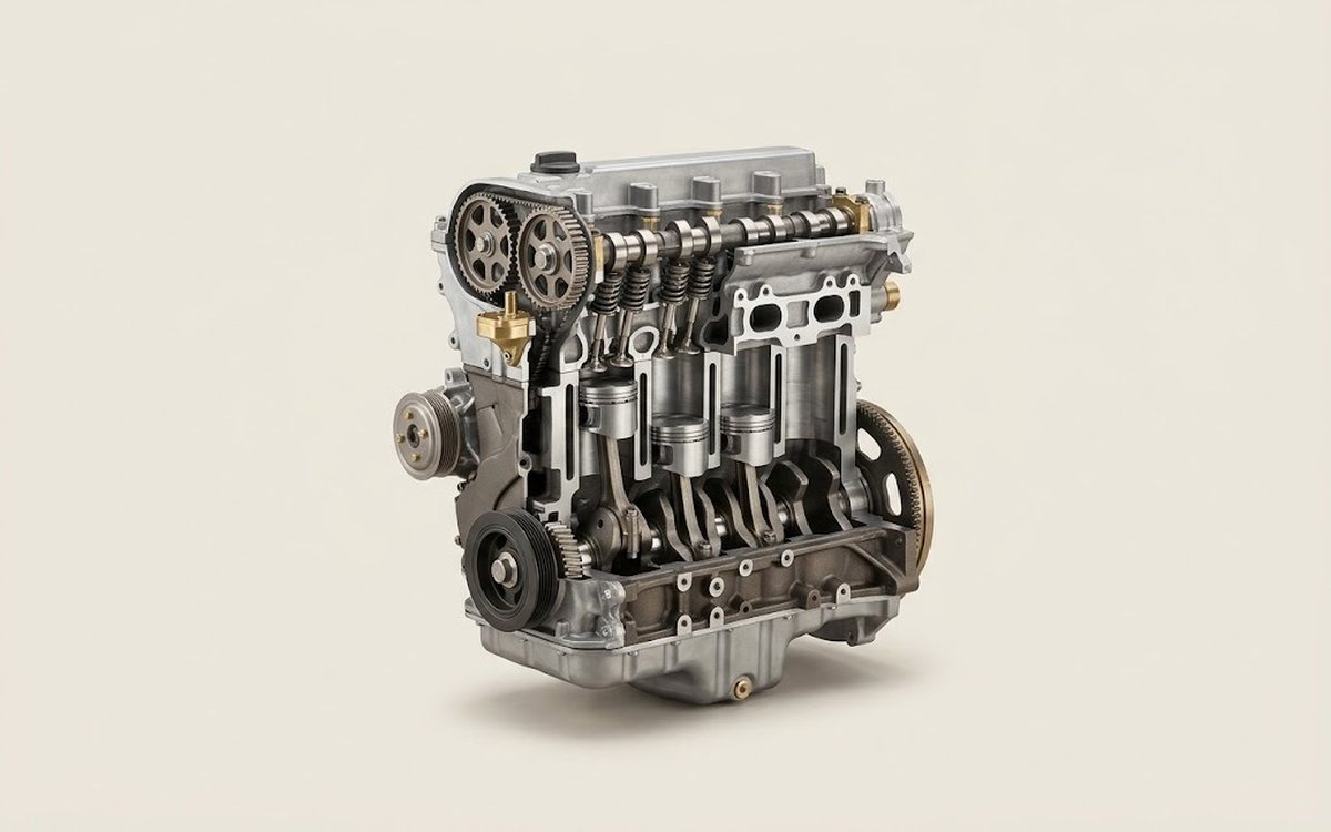 How it works · 3D
How a Car Engine Works
How the part you're working on actually works — in plain English, on a 3D model.
Open in 3D →