Autopapyrus · Volkswagen Transporter 1.9 TDI AXC (2003)
https://autopapyrus.com/guides/volkswagen/transporter/complete-engine-overhaul/
https://autopapyrus.com/guides/volkswagen/transporter/complete-engine-overhaul/
Compiled automatically from service literature and owner experience. Specs are for the typical configuration — check them against your exact car before you start.
Volkswagen Transporter 1.9 TDI AXC (2003): Complete Engine Overhaul
The AXC is an 8-valve 1.9 TDI diesel with unit injectors (79.5 mm bore, 95.5 mm stroke), a cast iron block, an aluminum cylinder head and a timing belt drive. An overhaul is justified when compression drops, the engine burns oil, there is heavy blow-by into the crankcase, or the main or rod bearings knock. The main risks are losing the timing marks during assembly, choosing the wrong oversize, overtightening or reusing stretch bolts, and dirt in the oil passages.
Part
- 🔩 Set of oversize pistons with rings and wrist pins for the chosen oversize (for a 79.5 mm standard bore, oversizes are usually +0.25 and +0.50 mm), main and rod bearing set, crankshaft thrust washers, engine gasket set with a cylinder head gasket of the correct thickness, new bolts for the cylinder head, connecting rods, main bearing caps and crankshaft pulley, valve stem seals, timing belt kit with tensioner/idler rollers and water pump, front and rear crankshaft seals, oil filter, engine oil meeting VW 505 01 (or 506 01), coolant
 There's a full repair manual for this car
Every system, wiring diagrams and torque specs — not just this job. Haynes and 21 more.
See manuals →
Step by step
18 steps- Preliminary inspection. Measure compression on a warm engine, check oil pressure and the amount of crankcase blow-by. If the only problem is worn valve stem seals (smoke at startup after the car has sat), it is enough to remove the cylinder head without opening up the bottom end. If blow-by is heavy, there is a lot of oil in the intercooler, and compression differs between cylinders, do a full overhaul.
- Preparation. Disconnect the negative battery terminal. Drain the oil and coolant. Move the front panel (radiator support/front cowl) to the service position, and remove the radiator, the intercooler with its pipes, and the skid plate. Disconnect the wiring harnesses, the fuel hoses (plug them), the turbocharger and cooling system pipes, the clutch actuation and the gearshift linkage.
- Engine removal. The T5 engine with the transmission comes out either downward together with the subframe or upward through the front panel opening, depending on your equipment. Support the powertrain with a jack beforehand, disconnect the mounts and lift it out carefully so as not to damage the harnesses and plastic parts. Separate the engine from the transmission, then remove the clutch and flywheel (use new flywheel bolts and tighten them to spec).
- Mount the engine on a stand or support. Remove the ancillaries: the turbocharger with the exhaust manifold, the power steering pump, the A/C compressor (without opening the refrigerant circuit), the alternator, the intake manifold and the fuel rail.
- Remove the timing belt covers, install the locking tools and set the marks (crankshaft and camshaft at TDC of cylinder 1), then remove the belt, rollers and pulleys. Remove the camshaft and rocker arms, carefully marking each unit injector and rocker arm by cylinder. Remove the injectors using the hold-down clamp, then cover the openings with clean plugs.
- Remove the cylinder head. Loosen the cylinder head bolts in the reverse of the tightening sequence, evenly and in several passes. The bolts are single-use, so replace them with new ones. Remove the gasket and check the head's flatness with a straightedge.
- Cylinder head inspection. Check flatness, cracks between the valve seats, valve guide clearances and the condition of the seats. Replace the valve stem seals with new ones: remove the valves with a valve spring compressor, and install the seals only through the protective sleeve (a protective cap on the stem tip) so they are not torn on the keeper grooves. If the guides or seats are worn, send the head to a machine shop. Replace the valves if the valve face or head is worn.
- Disassemble the bottom end. Remove the oil pan, oil pickup tube, oil pump and baffle plate. Mark the connecting rod caps, remove the caps and push the pistons with the rods out upward. Remove the main bearing caps and lift out the crankshaft. Lay the bearing shells out in order, since their wear will point to the cause of the problem.
- Measurement. Use a bore gauge to measure the cylinders along two axes at three levels, and assess out-of-roundness and taper. If wear is within the factory tolerance, you can get by with honing for standard rings. Otherwise, bore and hone to an oversize, the same for all cylinders. Choose the size based on the most worn cylinder. Give the block to the machine shop together with the pistons so the machinist can set the piston-to-cylinder clearance for your specific set. Use a micrometer to check the rod and main journals of the crankshaft: if wear exceeds the tolerance, have the journals ground to an undersize for the bearings, then fit new undersize bearings.
- Block preparation. After machining, wash the block with hot water and detergent, blow out all oil passages, clean the passages with a brush, and wipe the cylinder bores with a clean rag until the gray honing residue no longer comes off. Coat the cylinder walls with engine oil. Check and flush the piston cooling oil jets (this block has them). They must be clean, intact and undeformed.
- Assemble the rotating assembly. Install the main bearing shells (the upper ones with oil grooves go in the block, the lower ones in the caps), lubricate and lay in the crankshaft, and tighten the caps with new bolts to the factory spec (torque plus angle). Check the crankshaft end play (thrust washers); the crankshaft should turn freely. Use Plastigage to check the bearing clearances.
- Pistons. Fit the rings: measure the end gap in the cylinder and check the side clearance in the ring groove. Stagger the ring gaps around the piston, lubricate, compress the rings with the ring compressor and install the pistons according to the mark (the arrow on the piston crown points toward the timing belt side). Fit the rod bearings with oil, install the caps according to the marks, use new bolts, and tighten to spec (torque plus angle). Rotate the crankshaft after each piston.
- Replace the front and rear crankshaft seals and degrease the mating surfaces. Install the oil pump, the oil pickup tube with a new seal and the oil pan using sealant or a gasket according to the manufacturer's specification, tightening in several passes in a crisscross pattern.
- Cylinder head installation. Select the gasket based on piston protrusion above the block deck (measure with a dial indicator at TDC; the gasket thickness is identified by the marking, holes or notches). Boring and replacing the pistons will change the protrusion, so this measurement is mandatory. Tighten the new cylinder head bolts in several stages in a crisscross pattern following the diagram, with a final angle tightening (this engine family typically uses 4 stages with a total of roughly 180° of angle; take the exact torques and angles from the service manual for your engine). Never use old bolts or tighten by feel.
- Install the camshaft, rocker arms and unit injectors (with new O-rings and washers; install the injectors strictly according to the cylinder marks, and tighten the hold-down clamp to spec). Set the timing marks, then install a new belt, rollers and water pump. Turn the crankshaft by hand for 2 revolutions and recheck the marks. Install the protective covers.
- Ancillaries and installation. Assemble the manifolds with new gaskets, install the turbocharger (before installing it, pour oil into its oil inlet and flush the oil feed line, and replace the seals), then the ancillaries, clutch and flywheel. Install the engine, connect the transmission, mounts, harnesses, hoses, radiator and intercooler.
- Refilling and first start. Replace the oil filter and add oil (about 4-5 L (4.2-5.3 qt); check with the dipstick), then coolant. Bleed the fuel system until the flow is clean and free of air, disable the injectors/fuel supply relay and crank the engine with the starter until the oil pressure light goes out. Then start the engine without load and hold it at 1500-2000 rpm for about 10-15 minutes, watching the oil pressure and checking for leaks.
- Break-in. For the first 1000-1500 km, do not load the engine: no hard acceleration, no prolonged idling, no driving at maximum rpm and no towing. After 500-1000 km, change the oil and filter, then retighten whatever the service manual calls for. Keep an eye on the oil and coolant levels.
Common mistakes and warnings
- This is a complex job that requires precise measurements and specialized equipment. The bolts for the cylinder head, connecting rods, main bearing caps, flywheel and crankshaft pulley are single-use and are tightened with an angle turn. Take the torque and angle values for your engine from the manufacturer's service manual and never go by feel. If you have no experience building engines, leave the block machining and assembly to a specialized engine shop. The engine weighs roughly 150-180 kg (330-400 lb) together with the transmission, so use reliable lifting equipment.
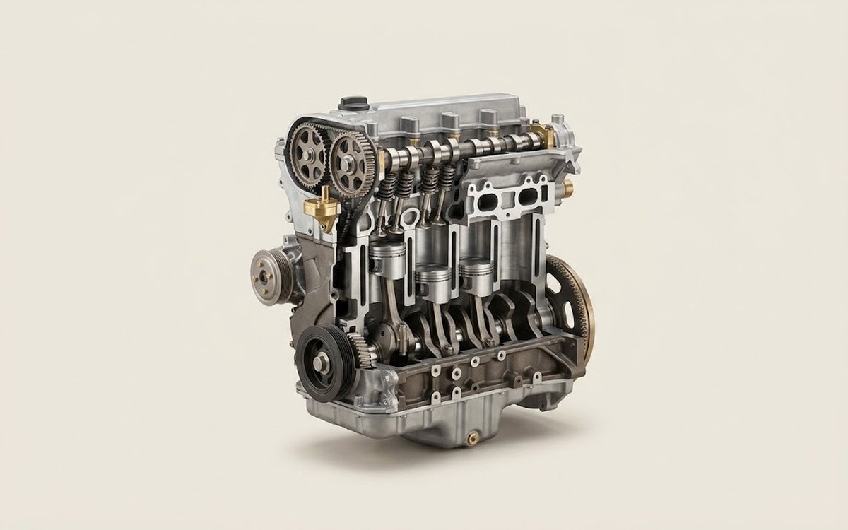 How it works · 3D
How a Car Engine Works
How the part you're working on actually works — in plain English, on a 3D model.
Open in 3D →