https://autopapyrus.com/catalog/daf/xf/guides/engine-overhaul-xf-105-2013/
DAF XF105 12.9 MX-340 (2013): Engine Overhaul
The MX-340 engine (12.9 L, 6 cylinders, 130 mm bore, 162 mm stroke, 17.5:1 compression ratio) has wet replaceable cylinder liners, so an overhaul includes replacing the liners and checking their protrusion above the block deck. The job is done with the engine removed or, if you have the experience and equipment, with the engine in the vehicle on a lift by tilting the cab. The tightening torques below are confirmed for MX-13 engines (including the 340 version); check all other values against the manufacturer's service manual tables.
Key figures
- Main bearing cap tighteningstep 29; a torque wrench and angle gauge are mandatory70 N·m (52 lb-ft), then 250 N·m (184 lb-ft), then an additional 150 degrees
- Connecting rod bolt tighteningstep 3050 N·m (37 lb-ft), then 130 N·m (96 lb-ft), then an additional 90 degrees
- Long cylinder head bolt (M18) tighteningstep 35; new bolts only70 N·m (52 lb-ft), then 250 N·m (184 lb-ft), then two additional 90-degree turns
- Short cylinder head bolt (M12) tighteningstep 3560 N·m (44 lb-ft), then an additional 120 degrees
- Cylinder bore and piston strokeused to select liners, pistons and rings (steps 26-30)130 mm and 162 mm
- Engine weightthis is the load on the overhead crane and the engine stand (steps 11-12)about 1180 kg (2,600 lb)
Check these values against the manufacturer’s specification for your vehicle before you start.
Parts
18| № | Part | Alternatives |
|---|---|---|
| 01 | Complete engine gasket set (upper and lower)Find on Amazon → | AlternativesElringVictor ReinzMahleFebi |
| 02 | Cylinder head gasket, Euro 5 (multi-layer steel)Find on Amazon → | AlternativesElringVictor ReinzMahleFebi |
| 03 | Cylinder head bolts (single-use, with thread sealant)setFind on Amazon → | |
| 04 | Connecting rod and main bearing cap bolts (single-use)if stretched beyond the limitFind on Amazon → | |
| 05 | Liner, piston and ring set (12.9 L, 130 mm cylinder bore)Find on Amazon → | AlternativesElringVictor ReinzMahleFebi |
| 06 | Main and connecting rod bearing shells (undersize)size per journal measurementsFind on Amazon → | |
| 07 | Crankshaft thrust washersFind on Amazon → | |
| 08 | Crankshaft front sealFind on Amazon → | AlternativesElringVictor ReinzMahleFebi |
| 09 | Crankshaft rear sealFind on Amazon → | AlternativesElringVictor ReinzMahleFebi |
| 10 | Liner O-ring setFind on Amazon → | AlternativesElringVictor ReinzMahleFebi |
| 11 | Oil pumpdepending on conditionFind on Amazon → | |
| 12 | Oil filterFind on Amazon → | |
| 13 | Engine oil meeting the DAF specification for Euro 5Find on Amazon → | |
| 14 | CoolantFind on Amazon → | |
| 15 | Water pumpFind on Amazon → | |
| 16 | ThermostatFind on Amazon → | |
| 17 | Accessory drive belt with pulleysFind on Amazon → | |
| 18 | Injectorsif faulty per bench testFind on Amazon → |
Amazon links search by the part name; use Amazon's fit check for your car before ordering. We may earn a commission from qualifying purchases.
Tools
15- Vehicle lift or inspection pit Amazon →
- overhead crane or hydraulic engine hoist Amazon →
- engine stand Amazon →
- torque wrench with a range up to 300 N·m (221 lb-ft) Amazon →
- angle gauge for angle-torque tightening Amazon →
- bore gauge and micrometers Amazon →
- dial bore gauge Amazon →
- dial indicator with stand Amazon →
- Plastigage Amazon →
- cylinder liner puller Amazon →
- seal installation drivers Amazon →
- socket set and ratchet Amazon →
- compression tester Amazon →
- multimeter Amazon →
- containers for draining oil and coolant Amazon →
Step by step
47 steps · 8 stagesStage 1 of 8 Diagnosis and preparation 5 steps
- Confirm that an overhaul is needed: measure cylinder compression, check oil consumption, look for oil in the cooling system and coolant in the oil, check crankcase blow-by, and check oil pressure on a warm engine.
- Read the fault codes with a diagnostic scan tool and record them. Check the injectors, turbocharger and EGR system: smoke is often not caused by the piston/cylinder group.
- Park the vehicle on level ground, place wheel chocks, and disconnect the battery (set the master switch to the "off" position).
- Drain the coolant and engine oil into separate containers. Remove the oil filter.
- Tilt the cab following the XF105 procedure and secure it with the support stay. Before doing so, remove any excess load from the cab and disconnect anything that obstructs tilting.
Stage 2 of 8 Engine removal 7 steps
- Remove the skid plate, the radiator shrouds and, if necessary, the charge air ducts. Disconnect the intercooler and radiator hoses, and remove the fan with its shroud.
- Disconnect the A/C hoses (after recovering the refrigerant, if you are removing the compressor) and the power steering hoses if they are in the way.
- Disconnect the fuel lines (supply and return) and plug the fittings. Disconnect the wiring harnesses, sensors, starter and alternator, and label the connectors.
- Remove the exhaust system: the downpipe and, if necessary, the SCR catalyst components (Euro 5). Disconnect the temperature and NOx sensors from the harness.
- Separate the transmission from the engine: support the transmission with a jack, remove the clutch housing bolts, and move the transmission rearward. Tighten the fasteners to the torque table in the service manual for that transmission.
- Attach the engine to the overhead crane with slings at the factory lifting eyes, take the load off the mounts, remove the engine mount fasteners, and carefully lift the engine out forward and up (through the opening with the cab tilted).
- Mount the engine on the stand and clean the outer surfaces of dirt.
Stage 3 of 8 Engine disassembly 8 steps
- Remove the accessories: turbocharger, manifolds, water pump, alternator, brackets, compressor, high-pressure fuel pump (if fitted), and injectors. Keep the fasteners sorted by assembly.
- Remove the cylinder head cover, rocker arms, pushrods or the camshaft with rocker arms (depending on engine version). Mark the position of each part and lay them out in cylinder order.
- Loosen the cylinder head bolts in the reverse of the tightening sequence, starting from the outer ones, and lift off the head with a crane. The head bolts must be replaced and must not be reused.
- Remove the oil pan, oil pickup tube and oil pump. Inspect the pan for metal shavings and metal dust: they show which bearing shells are worn.
- Remove the front cover, the timing drive and gears (engine with gear drive), and preserve the gear alignment marks (the marks on the teeth line up during assembly).
- Remove the flywheel with ring gear and the rear seal. Remove the connecting rod cap bolts and take out the pistons together with the connecting rods, numbering each assembly by cylinder.
- Remove the main bearing caps (numbered on the caps), lift out the crankshaft with a crane or with two people, and remove the bearing shells and thrust washers.
- Extract the liners with a puller. Clean the seats in the block of scale and corrosion, and check for cavitation and cracks.
Stage 4 of 8 Inspection and part preparation 6 steps
- Thoroughly wash the block and the oil passages, blow them out with compressed air, and check the flatness of the block deck with a straightedge and feeler gauge.
- Measure the crankshaft journals (main and rod) with a micrometer in two planes, and check out-of-round, taper and crankshaft runout. Tolerances and undersizes are per the manufacturer's service manual table. If a journal is out of tolerance, the shaft is ground to an undersize.
- Check the connecting rods: non-parallelism, bend, big-end out-of-round with the caps tightened, and small-end bushing clearance.
- Check the cylinder head: cracks (pressure test), flatness, valve seats and guides, and springs. Replace the guides and lap the valves if necessary.
- Test the injectors and fuel system components on a bench, and send them to a specialist shop if necessary.
- Install new liners with new O-rings, lubricating the rings with a thin layer of engine oil or a lubricant approved by the manufacturer. Do not allow the rings to twist during installation.
Stage 5 of 8 Block assembly 7 steps
- Install the liners in the block and check the liner protrusion above the block deck with a dial indicator at all cylinders. The protrusion tolerance and the difference between adjacent liners are per the DAF service manual table for the MX; if they are out of spec, change the shims or check the seating.
- Install the main bearing shells, lubricate the journals and shells with clean engine oil, and lay in the crankshaft.
- Install the thrust washers and the main bearing caps according to the marks. Tighten the main cap bolts in three stages: 70 N·m (52 lb-ft), then 250 N·m (184 lb-ft), then an additional 150 degrees. Check that the shaft turns freely after each cap, and measure the crankshaft end play against the service manual table.
- Install the pistons together with the connecting rods: stagger the ring gaps around the circumference, use a ring compressor, and orient the piston marks (arrow facing forward) per the service manual. Tighten the connecting rod cap bolts: 50 N·m (37 lb-ft), then 130 N·m (96 lb-ft), then an additional 90 degrees.
- Check the piston protrusion above the block deck (or the clearance to the head based on gasket thickness), and select a head gasket of the required thickness per the service manual table.
- Install the oil pump, oil pickup tube, and the oil pan with a new gasket. Bolt tightening is per the service manual.
- Install the rear seal and flywheel (bolts per the service manual, with a torque wrench and angle tightening if required), the front cover, and the timing drive, aligning the marks on the gears.
Stage 6 of 8 Cylinder head and valvetrain installation 5 steps
- Place the new head gasket on the clean, dry deck without applying sealant (unless the service manual requires it). Install the head onto the dowels.
- Tighten the new head bolts strictly following the service manual pattern. Long M18 bolts: stage 1 – 70 N·m (52 lb-ft), stage 2 – 250 N·m (184 lb-ft), stage 3 – an additional 90 degrees, stage 4 – another 90 degrees. Short M12 bolts: stage 5 – 60 N·m (44 lb-ft), stage 6 – an additional 120 degrees. See the MX service manual for the tightening sequence diagram.
- Install the pushrods or rocker arms and adjust the valve and injector clearances per the MX service manual table (perform the check on a cold engine with the piston of the relevant cylinder at TDC).
- Install the valve cover with a new gasket, the injectors with new washers and O-rings, and the fuel lines. Tightening of the injectors and fittings is per the service manual.
- Install the manifolds, the turbocharger with new gaskets, the water pump, the thermostat, and the hoses.
Stage 7 of 8 Installation in the vehicle 4 steps
- Install a new clutch on the engine (replacing the clutch and release bearing is recommended), and check the disc alignment.
- Lower the engine into place, connect it to the transmission, and secure the mounts. Tighten all fasteners per the service manual.
- Reconnect the fuel lines, wiring harnesses, cooling system hoses, charge air ducts, exhaust, radiator, intercooler, and fan.
- Fill with oil and coolant meeting the DAF specification to the level marks. Install a new oil filter.
Stage 8 of 8 First start and break-in 5 steps
- Before starting, crank the engine with the starter with the fuel supply disabled until oil pressure appears. Check for leaks.
- Start the engine, warm it up at idle to operating temperature, and check oil pressure, joint sealing, sensor readings, and the absence of fault codes.
- Bleed the cooling system to remove air, and top off the coolant.
- Break-in: for the first 1,000-1,500 km (620-930 miles), avoid full loads and prolonged operation at maximum rpm, avoid hard launches, and avoid idling for more than 10 minutes.
- After break-in, change the oil and oil filter, check the valve clearances (per the service manual), re-check the external fasteners, and check for fault codes.
Common mistakes and warnings
- This is a complex job that requires precise measuring tools and equipment capable of removing an engine weighing about 1180 kg (2,600 lb)
- It is not recommended without experience; if you lack the equipment, leave the work to a specialist repair shop
- Always work with the cab tilted and secured on a reliable support, and never stand under a raised engine
- The cylinder head, main cap and connecting rod bolts are tightened with an additional angle and in most cases are replaced with new ones
- The torque values below are confirmed for the MX-13 and apply to the MX-340 engine; check clearance tolerances, liner protrusion and crankshaft journal dimensions against the manufacturer's service manual tables
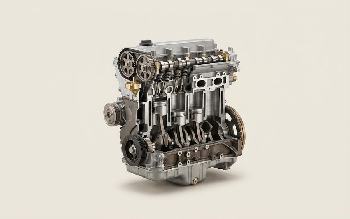 How it works · 3D
How a Car Engine Works
How the part you're working on actually works — in plain English, on a 3D model.
Open in 3D →
Spotted a mistake? Tell us →
Our articles
 Brand stories
The History of the DAF Brand
DAF Trucks NV is a Dutch truck manufacturer and a division of PACCAR. The company's slogan is "Driven by quality."
Read →
 Garage
Fuel Quality Indicators: What Octane and Cetane Numbers Mean
What is an octane number? What about a cetane number? Which fuel should you choose for a high-compression engine?…
Read →
 Before you buy
How to Pick Up Your Car from the Dealership the Right Way
If you've decided to buy a car from a dealership, it isn't enough to simply choose a model you like, pay for it, and…
Read →