https://autopapyrus.com/catalog/jeep/grand-cherokee/guides/cylinder-head-repair-valve-replacement-and-valve-stem-seal-replacement/
Jeep Grand Cherokee 3.6 Pentastar (2012): Cylinder Head Repair, Valve Replacement and Valve Stem Seal Replacement
Cylinder head work on the 3.6 Pentastar (a V6 engine with a chain-driven twin-cam setup on each head, 4 valves per cylinder, and roller rocker arms with hydraulic lash adjusters) requires removing the manifold, covers, cam phasers and camshafts, and often the head itself. The most common reasons for the repair are oil consumption (valve stem seals), rocker arm and cam lobe wear, and the left cylinder head defect on early 2011-2013 engines. If you only need valve stem seals or a single valve replaced and the head can stay on, the job is done on the engine with the camshafts removed. If the sealing surface is warped or cracked, or a valve seat is burned, the head must come off.
Key figures
- Number of rocker arms per head12 pieces. Replace them all at once, not just the one that failed (step 11), because the rest have the same service life.
Check these values against the manufacturer’s specification for your vehicle before you start.
Parts
14| № | Part |
|---|---|
| 01 | Cylinder head gasket setleft and rightFind on Amazon → |
| 02 | Cylinder head bolts (set)Find on Amazon → |
| 03 | Valve stem seals (24-valve set)Find on Amazon → |
| 04 | Intake valvesif wornFind on Amazon → |
| 05 | Exhaust valvesif wornFind on Amazon → |
| 06 | Valve springsFind on Amazon → |
| 07 | Valve keepersFind on Amazon → |
| 08 | Roller rocker armsFind on Amazon → |
| 09 | Hydraulic lash adjustersFind on Amazon → |
| 10 | Valve cover gasketsFind on Amazon → |
| 11 | Intake manifold gasketFind on Amazon → |
| 12 | Engine oilFind on Amazon → |
| 13 | Oil filterFind on Amazon → |
| 14 | CoolantFind on Amazon → |
Amazon links search by the part name; use Amazon's fit check for your car before ordering. We may earn a commission from qualifying purchases.
Tools
11- Socket set and ratchet Amazon →
- torque wrenches (in N·m and in inch-pounds for the camshaft caps) Amazon →
- timing and shaft locking tools (Pentastar kit) Amazon →
- phaser puller Amazon →
- valve spring compressor Amazon →
- valve stem seal installer Amazon →
- feeler gauges and micrometer Amazon →
- paint marker Amazon →
- sealant Amazon →
- red assembly lube Amazon →
- thread repair kit Amazon →
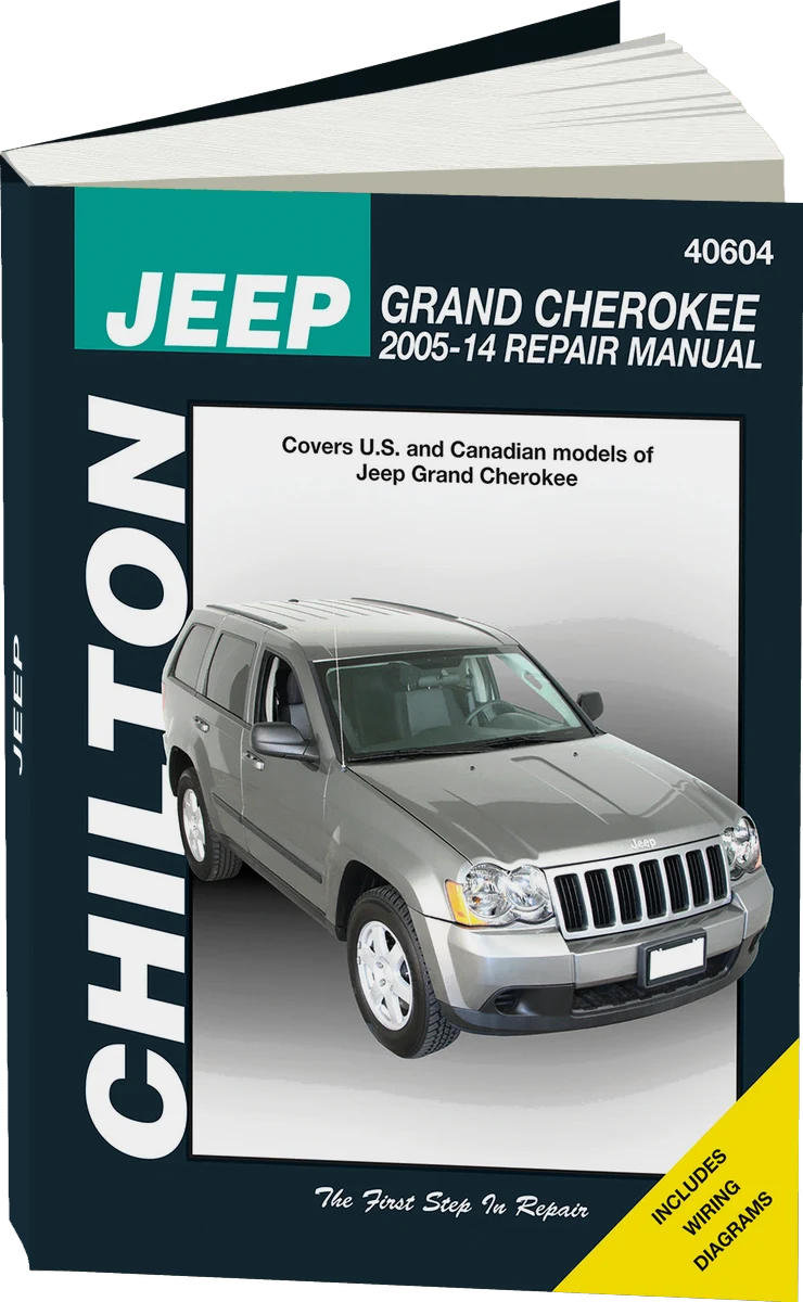 There's a full repair manual for this car
Every system, wiring diagrams and torque specs — not just this job. Chilton and 6 more.
See manuals →
Step by step
17 steps- Preparation. Disconnect the negative battery terminal and drain the coolant and engine oil. Set out containers for parts, mark the connectors and hoses you remove with a paint marker, and take photos. Work on a clean bench.
- Access. Remove the engine cover, the air duct, and the upper intake manifold together with the throttle body. Double-check that you disconnected all the hoses at the throttle body: a missed hose causes a vacuum leak and surging idle on the first start.
- Remove the ignition coils and spark plugs from the head you are working on (the spark plugs have M12x1.25 threads, and threads in aluminum are easily damaged, so remove them with the engine warm, not hot), plus the camshaft position sensors and wiring harnesses.
- Remove the valve cover. It is seated on factory sealant: pry it up with wooden wedges without scratching the sealing surface. The oil dipstick bracket bolt near the transmission bell housing is hard to reach: use long extensions and a universal joint, and be careful not to cross-thread it during installation.
- Install the timing and shaft locking tools in the special holes so the chain cannot jump. This is the hardest stage: the locking tools do not always go in on the first try, so do not rush. Mark the chain and phaser timing marks with paint.
- Remove the cam phasers with a large socket, then the bearing caps and camshafts. Lay the caps out in strict order. Remove all 12 rocker arms from the head you are working on and lay them out in order, along with the hydraulic lash adjusters. Inspect the lobes: a bright spot on the edge of a lobe and a step you can feel with a fingernail mean wear, and if the wear is noticeable, replace the camshaft.
- Valve stem seals only (if the valves and head are in good condition): the head stays on the engine, and the cylinder is set to a position where the valves are kept from dropping (piston at TDC, with air pressure through the spark plug hole or a rope). Install the valve spring compressor, compress the spring, remove the keepers, then take off the retainer and spring. Then pull off the old seal and install the new one through the protective sleeve onto the stem, lightly lubricated with oil. Reassemble the valve, check that the keepers are seated, and tap the retainer.
- Head removal (if valves, seats or the head itself need repair): disconnect the exhaust manifold and the cooling system hoses, then take the chain off the head and secure it so it cannot fall. Loosen the head bolts in the reverse of the tightening sequence, evenly over several passes, then remove the head. The exact sequence and loosening stages are given in the manufacturer's service manual.
- Head inspection: clean the sealing surface of gasket residue with a plastic scraper, check flatness with a straightedge and feeler gauge, and check for cracks (pressure test). The head bolt threads in aluminum are prone to stretching: if they are damaged, use a thread repair kit (for example, M12x1.5 for the head bolts). Check the valve guides, the seats, the valve stem-to-guide clearance and the valve runout.
- Valves: disassemble the valves, inspect the heads and faces, and replace any that are burned or worn. Lap the valve to the seat (or have the seats and faces machined) and check the seal with solvent or vacuum. Check allowable dimensions and clearances against the manufacturer's specifications.
- Install new valve stem seals on all 24 valves and reassemble the head: springs, retainers, keepers. Replace the hydraulic lash adjusters and rocker arms (it is recommended to replace all 12 rocker arms on the head as a set rather than one at a time, because the rest have the same service life).
- Head installation: fit new gaskets the correct way around (marked left/right) and new head bolts (they are generally single-use, but confirm in the service manual). Tighten strictly following the sequence and stages in the manual: the torque and angle for the head bolts are given in the service manual, so check the exact value against the manufacturer's specifications. Lubricate the threads and the underside of the bolt heads with oil as instructed.
- Camshaft installation: lubricate the journals, lobes and rocker arms with red assembly lube (the rocker arms can be soaked in oil before installation), install the camshafts according to the marks, and the bearing caps in their marked order. The caps are tightened to a low torque, in inch-pounds (per the manual), in several passes from the center outward, using a torque wrench.
- Install the cam phasers according to the marks and tighten the bolts to the specified torque. Remove the locking tools, turn the crankshaft 2 revolutions, and recheck that the marks line up and the locking tools fit. If the marks do not line up, disassemble and repeat.
- Reassemble in reverse order: valve cover with new sealant and gasket (torque per the manual, tighten in the sequence from the center out, lightly, with the plastic cover bolts having retaining sleeves), coils, spark plugs (torque per the manual), intake manifold with a new gasket, throttle body, hoses and connectors.
- Filling and starting: add coolant and bleed the air from the system, fill with fresh oil and install a new filter. Crank the engine with the starter without starting it until oil pressure appears, then start it. Listen for noises, and check for leaks and fault codes.
- Final check: warm the engine to operating temperature, let it idle, check for leaks and fluid levels, and clear the fault codes. After 500-1000 km (300-600 miles), check the oil and coolant levels and inspect again for leaks.
Common mistakes and warnings
- This is a difficult job: a mistake in timing installation or head bolt tightening will destroy the engine
- If you lack experience disassembling engines, the special tools for locking the timing, and torque wrenches, leave it to a specialist repair shop
- Torque values, sequences, clearances and dimensions are not given in this guide: take the exact values from the manufacturer's service manual for the 3.6L Pentastar and do not substitute approximate ones
- Do not reuse old head bolts if the manual requires replacing them
Spotted a mistake? Tell us →
Our articles
 Brand stories
The History of the Jeep Brand
It's hard to find anyone who isn't at least vaguely familiar with Jeep vehicles. The name has become a generic term for…
Read →
 Garage
Fuel Quality Indicators: What Octane and Cetane Numbers Mean
What is an octane number? What about a cetane number? Which fuel should you choose for a high-compression engine?…
Read →
 Before you buy
How to Pick Up Your Car from the Dealership the Right Way
If you've decided to buy a car from a dealership, it isn't enough to simply choose a model you like, pay for it, and…
Read →