Autopapyrus · Kia Picanto 1.0/1.1 (2008)
https://autopapyrus.com/catalog/kia/picanto/guides/manual-transmission-overhaul-with-bearing-and-synchronizer-replacement/
https://autopapyrus.com/catalog/kia/picanto/guides/manual-transmission-overhaul-with-bearing-and-synchronizer-replacement/
Compiled automatically from service literature and owner experience. Specs are for the typical configuration — check them against your exact car before you start.
Kia Picanto 1.0/1.1 (2008): Manual Transmission Overhaul, Bearings and Synchronizers
The Picanto SA with 1.0 and 1.1 engines uses the M5CF1 five-speed manual transmission: a two-piece case (clutch housing and transmission case), cable-operated shifter, and hydraulic clutch. Dry weight of the transmission is about 41.6 kg. The torque values below are approximate; verify the exact values against the manufacturer's specifications. This guide covers a transmission that has been removed from the vehicle; repair with the transmission in the car is not possible.
Key figures
- Transmission weightabout 41.6 kg. The transmission is heavy, so remove it only on a transmission jack with a strap (steps 13, 40)
- Case typetwo pieces (clutch housing and transmission case). This is the order of separation in steps 16 and 19
Check these values against the manufacturer’s specification for your vehicle before you start.
Diagram: where the pin, selector and shafts are in an opened gearbox and how to separate the housing halves
Tap to enlarge
- 1Differential with the big ring gear: sits in the housing, lifted out separately from the shafts.
- 2Input and output shaft block: stepped gears with synchronizers, lifted out together without disassembly.
- 3Gear selector mechanism: lever, spring and detent bolt. Remove it and keep the springs and balls from getting lost.
- 4Dowel pin: a cylinder on the split plane that aligns the housing halves.
- 5Split plane with bolt holes and a layer of blue sealant: remove old sealant and degrease.
- 6Second housing half: bolts around the edge, a socket for the pin. Separate the halves by prying at the special spots.
Parts
10| № | Part | Alternatives |
|---|---|---|
| 01 | M5CF1 manual transmission bearing overhaul kit (input and output shaft bearings, gear needle bearings, differential bearing)Find on Amazon → | AlternativesSKFFAGNSKINA |
| 02 | Synchronizer kit (rings for 1st, 2nd and 3rd gears: double cone; 4th and 5th: single cone)sleeve and hub if wornFind on Amazon → | |
| 03 | Left axle sealFind on Amazon → | |
| 04 | Right axle sealFind on Amazon → | |
| 05 | Shift/select rod sealFind on Amazon → | |
| 06 | Snap ring and spring pin setFind on Amazon → | |
| 07 | Case split line sealantFind on Amazon → | |
| 08 | Transmission fluid GL-4 (low viscosity)Find on Amazon → | |
| 09 | Clutch release bearingreplace while the transmission is outFind on Amazon → | |
| 10 | Clutch discreplace while the transmission is outFind on Amazon → |
Amazon links search by the part name; use Amazon's fit check for your car before ordering. We may earn a commission from qualifying purchases.
Tools
15- lift or pit Amazon →
- transmission jack or transmission support stand Amazon →
- jack stands Amazon →
- socket and wrench set Amazon →
- torque wrench Amazon →
- bearing puller (2-3 jaw) Amazon →
- press or driver set Amazon →
- snap ring pliers Amazon →
- drift punches Amazon →
- caliper Amazon →
- dial indicator Amazon →
- feeler gauges Amazon →
- rubber mallet Amazon →
- oil drain pan Amazon →
- parts trays Amazon →
 There's a full repair manual for this car
Every system, wiring diagrams and torque specs — not just this job. Haynes AutoFix (online) and 2 more.
See manuals →
Step by step
48 steps · 8 stagesStage 1 of 8 Preparation and diagnosis 4 steps
- Identify the symptoms: noise in neutral (input shaft bearing), whine in gear (output shaft bearings, gears), grinding when shifting (synchronizer rings), popping out of gear. If the problem is only the clutch, you do not need to disassemble the transmission.
- Prepare a clean work area and containers for parts. Take photos of the assemblies as you disassemble them: the order of washers, rings and forks matters during reassembly.
- Buy the overhaul kit, seals, snap rings, sealant and fluid in advance. Snap rings and spring pins are best not reused after disassembly.
- Disconnect the battery (negative terminal first). Warm up the transmission with a short drive so the fluid drains more easily.
Stage 2 of 8 Removing the transmission from the vehicle 10 steps
- Raise the vehicle on a lift, remove the front wheels and the engine undercover (if fitted).
- Drain the fluid from the transmission through the drain hole (hex or wrench-type plug). Install a new plug washer during reassembly; approximate plug torque is 30-45 N·m (22-33 lb-ft).
- Remove the air filter with its duct, the battery terminals and the battery with its tray (if in the way), and disconnect the reverse light switch connector.
- Disconnect the select cable and the shift cable from the levers on the transmission (remove the retaining clips and the cable housing retainers).
- Disconnect the clutch hydraulics: remove the slave cylinder from the transmission without disconnecting the hose, and hang it to one side. If you do disconnect the hose, collect the brake fluid.
- Remove the starter (two or three bolts), disconnect the speed sensor and the harness brackets.
- Disconnect the lower ball joints or control arms from the steering knuckles (or disconnect the stabilizer bar links and control arms), pull the driveshafts out of the transmission, and hang them with wire. Tighten the hub nuts and ball joint nuts to specification during reassembly.
- Install a support under the engine, remove the subframe or crossmember (if it is in the way), and remove the transmission mount (mount bracket bolts approximately 60-80 N·m (44-59 lb-ft)) and the side mount.
- Position a transmission jack under the transmission and secure it with a strap. Remove the bolts securing the transmission to the engine, move the transmission rearward until the input shaft clears the clutch disc, and lower it.
- Remove the clutch fork and release bearing, and inspect the disc, pressure plate and flywheel; replace them if worn.
Stage 3 of 8 Disassembling the transmission 7 steps
- Clean the transmission on the outside and secure it on a stand on the workbench so the case is not damaged.
- Remove the clutch housing from the transmission (bolts around the perimeter), then remove the fork, release bearing and guide sleeve.
- Remove the shift levers and select mechanism, the rod detents, and the detent springs and balls. Make sure the springs and balls do not get lost.
- Remove the reverse light switch and the plugs, and remove the rear bearing cover or rear cover, if fitted.
- Remove the bolts of the split line between the transmission case and the clutch housing, and carefully separate the halves by prying at the designated points (do not drive a wedge into the mating surface).
- Remove the shift forks and rods, and mark their positions. Lift out the input and output shaft assembly together without taking it apart, and the differential separately.
- Remove the differential from the case, drive out the axle seals, and carefully inspect the differential bearings and the final drive (ring gear and the gear on the output shaft).
Stage 4 of 8 Disassembling the shafts 6 steps
- Clamp the input shaft in a vise with soft jaws, remove the snap ring and thrust washer, then pull off the (front) bearing with a puller, followed by the drive gears, synchronizer sleeves and rings. Lay the parts out on a clean cloth in the order of removal.
- On the output shaft, remove in sequence the snap rings, bearing, gears, needle bearings, synchronizer rings, sleeves and hubs. Record the orientation of each sleeve and hub (marks, position of the protrusions).
- Inspect the gears: teeth for chipping, flaking and pitting; the journals for the needle bearings for scoring; the gear cones for wear and glazing.
- Check the synchronizer rings: replace them if the teeth are rounded, or the working cone is smooth and glossy with no grooves. When fitted onto the gear cone, there should be a noticeable gap between the ring and the gear faces (minimum value per the manufacturer's specification, approximately 0.5-1.0 mm). For the double-cone gears (1st, 2nd, 3rd), check all three rings.
- Check the synchronizer sleeves and hubs: tooth wear, dents on the splines, and free sliding of the sleeve over the hub. Replace worn sleeves and hubs as a set.
- Check the bearings: turn them by hand; they should spin without roughness or play. Replace all bearings in the overhaul kit, even if some of them look fine. Always replace the needle bearings.
Stage 5 of 8 Replacing parts and reassembling the shafts 5 steps
- Lubricate all parts with clean transmission fluid. Install the new needle bearings and gears on the output shaft, then the synchronizer rings, hubs and sleeves, in the reverse order of disassembly.
- Press the new bearings on with a driver against the inner race; apply force only to the race that is seated on the shaft, never through the balls or rollers.
- Install new snap rings in the grooves. Check the gear axial play with a feeler gauge: values per the manufacturer's specification, typically 0.1-0.4 mm for the output shaft gears; if out of tolerance, select thrust washers or rings of the appropriate thickness.
- Assemble the input shaft in the same sequence, and check that the gears turn freely, the synchronizer sleeves travel properly, and nothing binds.
- Replace the differential bearings (press on using a driver against the inner race), and check the ring gear bolt torque (approximately 90-120 N·m (66-89 lb-ft), or per specification if needed). Check the differential bearing preload per specification (select shims if necessary).
Stage 6 of 8 Reassembling the transmission 6 steps
- Clean the old sealant off the mating surfaces of the housings and degrease them. Press in the new axle seals, the rod seal and the input shaft seal using a driver of the correct diameter, and lubricate their lips.
- Install the differential, then the assembled shaft block with the forks and rods. Make sure the forks engage the sleeve grooves and the rods are in the correct positions.
- Apply a thin, even layer of sealant to the split line, align the case halves on the dowels, and tighten the bolts in a crisscross pattern. Case bolt torque is approximately 20-30 N·m (15-22 lb-ft) (exact value per specification).
- Install the rod detents (balls and springs), the select mechanism, the levers and the covers. Check that all gears engage by turning the input shaft by hand: the gears engage cleanly, the shaft turns freely in neutral, and nothing binds.
- Install the clutch housing (torque per specification, approximately 40-50 N·m (30-37 lb-ft)) and the clutch fork with a new release bearing, lubricated with spline grease.
- Pour in some of the fluid to check and turn the shaft; the remaining fill is done per specification after installation.
Stage 7 of 8 Installing in the vehicle 6 steps
- Install the new clutch disc, centering it with an alignment tool (if replacing), and the pressure plate to the specified torque, and apply a thin layer of high-temperature grease to the input shaft splines.
- Raise the transmission with the jack, align the input shaft splines with the disc (the shaft must not hang on the disc), bring the transmission up to the engine, and tighten the bolts securing it to the engine to approximately 40-60 N·m (30-44 lb-ft) (per specification).
- Install the mounts and brackets, tighten the transmission mount to approximately 60-80 N·m (44-59 lb-ft), and tighten the subframe and control arms per specification. Install the starter.
- Insert the driveshafts with new seals (and new retaining rings on the splines if needed), and reconnect the ball joints and stabilizer links. Reconnect the clutch slave cylinder, the select and shift cables, the reverse light switch and the connectors.
- Fill with transmission fluid to the lower edge of the fill hole (about 1.9 L (2.0 qt) as a guide; exact value per specification) and tighten the plugs. Install the wheels and tighten the wheel nuts in a crisscross pattern to approximately 90-110 N·m (66-81 lb-ft).
- If you opened the clutch hydraulics, bleed them with DOT 4 brake fluid until the pedal feel is firm with no air.
Stage 8 of 8 Checking 4 steps
- Connect the battery. With the engine off, press the clutch several times and check that all gears engage and that the cable adjustment is correct.
- Start the engine and check operation in neutral and with the clutch pressed while stationary: no noise, no pedal vibration, and gears engage without grinding.
- Take a test drive of 10-15 km, checking engagement and disengagement of all gears, and listening for noise, whine and popping out of gear. Do not stress the transmission with hard launches for the first 500-1000 km.
- After some mileage, inspect the transmission for leaks at the seals and the split line, check the fluid level and top up if necessary.
Common mistakes and warnings
- Removing and disassembling the transmission is heavy work: the unit weighs about 41.6 kg, so use a transmission jack and a safety strap
- If you lack experience in setting clearances, pressing on bearings and selecting shims, it is better to leave the disassembly to a specialist shop: an error in bearing preload or clearances will cause the transmission to fail again
- Work only on solid jack stands, never under a jack alone
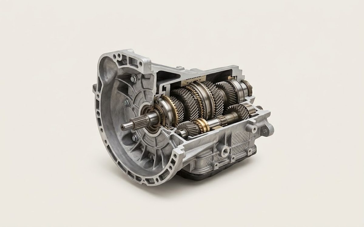 How it works · 3D
How a Manual Transmission Works
How the part you're working on actually works — in plain English, on a 3D model.
Open in 3D →