Autopapyrus · Mazda Axela (3rd generation, BL)
https://autopapyrus.com/catalog/mazda/axela/guides/front-subframe-replacement/
https://autopapyrus.com/catalog/mazda/axela/guides/front-subframe-replacement/
Compiled automatically from service literature and owner experience. Specs are for the typical configuration — check them against your exact car before you start.
Mazda Axela (3rd generation, BL): Front Subframe Replacement
On the BL, the subframe carries the lower control arms, the sway bar, and the rack-and-pinion steering gear with electric power steering. It is removed after impact deformation, for corrosion, or to replace bushings. The exact procedure for this specific engine is not documented in open sources, so what follows is the general principle for front-wheel-drive cars with McPherson struts, and torque values are given as ranges.
Parts
4| № | Part |
|---|---|
| 01 | Front suspension subframe assemblyFind on Amazon → |
| 02 | Lower control arm bushingsif wornFind on Amazon → |
| 03 | Subframe mounting boltssingle-use, if specifiedFind on Amazon → |
| 04 | Sway bar linksrecommended to replace at the same timeFind on Amazon → |
Amazon links search by the part name; use Amazon's fit check for your car before ordering. We may earn a commission from qualifying purchases.
Tools
9- Vehicle lift or jack stands and body supports Amazon →
- hydraulic jack or subframe stand Amazon →
- sockets and wrenches 12-21 mm Amazon →
- Torx sockets (for the splash shield and fender liners) Amazon →
- torque wrench Amazon →
- breaker bar or lug wrench Amazon →
- ball joint separator Amazon →
- pry bar Amazon →
- marking supplies (marker, paint). A spring compressor is not needed Amazon →
Step by step
12 steps- Raise the vehicle on a lift or stands with the wheels pointing straight ahead. Remove the front wheels and the lower engine splash shield. Disconnect the negative battery terminal.
- Lock the steering wheel in the straight-ahead position (do not turn it after removing the shaft, to avoid damaging the airbag clockspring). Remove the bolt that secures the lower steering shaft joint to the steering rack and move the shaft aside. Mark the relative position of the shaft and the splines.
- Disconnect the sway bar links from the sway bar, holding the stud with a wrench. Remove the ball joint nuts from the steering knuckles and release the ball joints from the control arms. Use a ball joint separator if needed.
- Disconnect the connectors and wiring harnesses attached to the subframe and the rack (electric power steering, sensors) and move them aside. If they are in the way, remove the front section of the exhaust system or the front pipe, and disconnect the torque rod (rear engine mount link) from the subframe.
- Mark the position of the subframe relative to the body with a marker. This is important for preserving wheel alignment angles; when reinstalling, the marks will line up the subframe position.
- Place a jack or subframe stand under the subframe and secure it firmly. If the subframe supports the powertrain through mounts, support the engine from below or take the load off with a support bar.
- Remove the bolts that secure the subframe to the body (usually four main bolts, sometimes additional brackets and braces). Lower the subframe slowly, watching the wiring harnesses, the rack lines and the sway bar.
- Remove the rack, sway bar and lower control arms from the subframe (if you are replacing only the subframe, transfer all components to the new one). Inspect the arms, bushings and tie rods, and replace any worn parts.
- Install the subframe in reverse order, aligning it with the marks. Tighten the body mounting bolts by hand first, then do the final tightening in two stages. The subframe bolt torque, as a typical figure for cars in this class, is 100-150 N·m (74-111 lb-ft); the exact value and any additional angle tightening should follow the manufacturer's specification. Tighten the ball joints, sway bar links, rack bolts and arm bolts to specification; do the final tightening of the arm bolts with the vehicle on its wheels, when the suspension is loaded.
- Reconnect the steering shaft using the marks and tighten the joint bolt (approximately 25-35 N·m (18-26 lb-ft); confirm with the specification). Reinstall the exhaust and splash shield, and tighten the wheel nuts in a crisscross pattern (about 100-110 N·m (74-81 lb-ft)).
- Reconnect the battery and check that the steering wheel is straight and that there are no EPS or ABS warnings on the instrument cluster. Take a test drive.
- Be sure to have a wheel alignment performed (toe and camber).
Common mistakes and warnings
- This job involves the steering and load-bearing suspension components
- If you lack the experience and equipment to remove the subframe safely and to adjust the alignment, leave it to a repair shop
- Never work under a vehicle supported only by a jack
- Do not turn the steering wheel while the steering shaft is disconnected, or you may damage the airbag clockspring
- A subframe deformed in a collision should be replaced rather than straightened
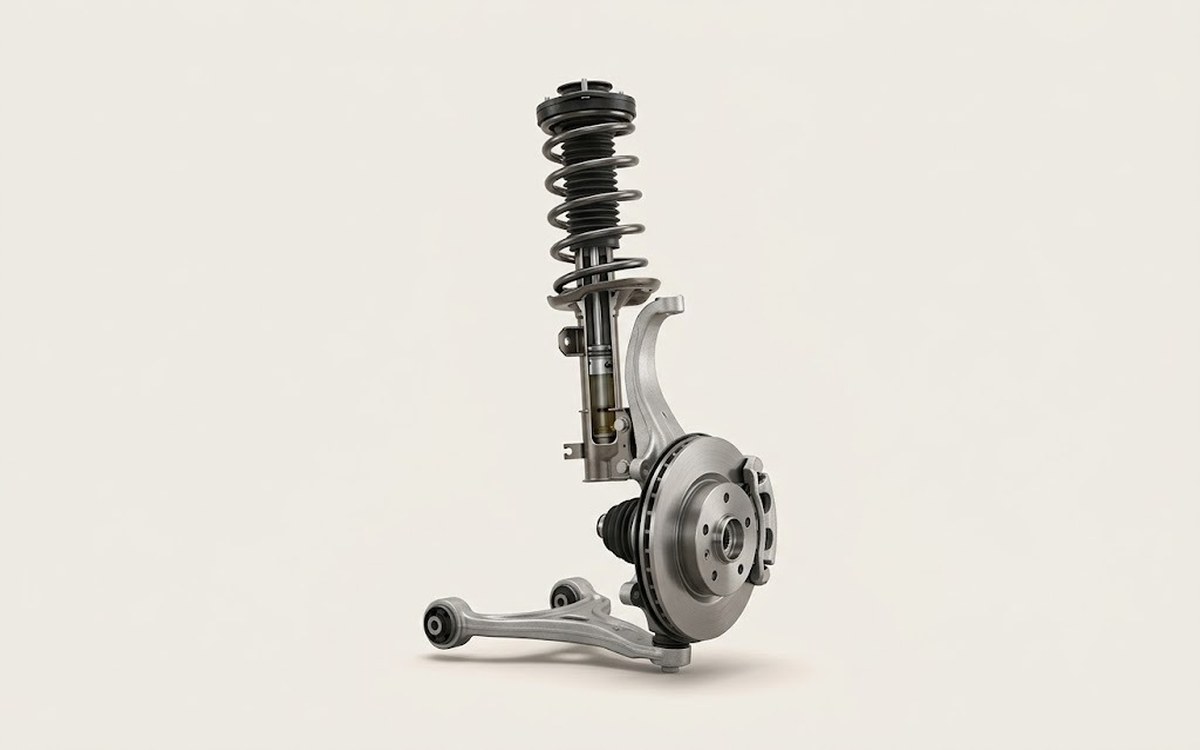 How it works · 3D
How Car Suspension Works
How the part you're working on actually works — in plain English, on a 3D model.
Open in 3D →
Spotted a mistake? Tell us →
Our articles
 Brand stories
The History of Mazda
It's hard to find anyone today who would dispute that cars from the Japanese company Mazda are among the most beautiful…
Read →
 Garage
Fuel Quality Indicators: What Octane and Cetane Numbers Mean
What is an octane number? What about a cetane number? Which fuel should you choose for a high-compression engine?…
Read →
 Before you buy
How to Pick Up Your Car from the Dealership the Right Way
If you've decided to buy a car from a dealership, it isn't enough to simply choose a model you like, pay for it, and…
Read →