https://autopapyrus.com/catalog/mitsubishi/pajero-sport/guides/diagnosing-a-front-suspension-knock/
Mitsubishi Pajero Sport 2.5 DI-D 4D56 (2012): Diagnosing a Front Suspension Knock
On the Pajero Sport II (KH) with the 4D56 engine, a knock in the front suspension is most often caused by worn sway bar bushings and sway bar links, and less often by worn ball joints and control arm bushings. The independent front suspension with torsion bars requires a step-by-step check of every component to pinpoint the source of the knock.
Parts
6| № | Part | Genuine part no. |
|---|---|---|
| 01 | Sway bar bushingsfront, set, if faultyFind on Amazon → | |
| 02 | Sway bar linksrear, if faultyFind on Amazon → | |
| 03 | Upper ball jointif faultyFind on Amazon → | 4010A099 |
| 4010A137 | ||
| 04 | Lower ball jointif faultyFind on Amazon → | 4013A314 |
| 05 | Control arm bushingsif faultyFind on Amazon → | MR992256 |
| 06 | Strut mount bearingsif faultyFind on Amazon → | MR992326 |
Amazon links search by the part name and genuine number; use Amazon's fit check for your car before ordering. We may earn a commission from qualifying purchases.
Part numbers are from the manufacturer's original catalogue. Check them against your VIN before ordering.
Tools
6Read the codes yourself
A scanner plugged into the OBD2 port under the dashboard shows which fault codes the car has stored, before you buy any parts. Cars sold in the US from 1996, and petrol cars in Europe from 2001 (diesels from 2004), have this port.
- Basic code reader, about $20–40: reads and clears engine codes Amazon →
- Bluetooth scanner with a phone app, about $30–100: live sensor data, and on many cars ABS and airbag codes too Amazon →
Check that the scanner lists your make and model year before you buy. We may earn a commission from qualifying purchases.
 There's a full repair manual for this car
Every system, wiring diagrams and torque specs — not just this job. Haynes AutoFix (online).
See manuals →
Step by step
10 steps- Drive the vehicle onto an inspection pit or lift, set the parking brake, and place wheel chocks under the rear wheels.
- From underneath, inspect the front sway bar bushings (the rubber brackets on the bar, about 20 mm in diameter). Cracks, tears, and deep grooves indicate wear. If the bushing is badly worn, it will move freely on the bar.
- Check the sway bar links (the vertical rods between the control arm and the sway bar). Grab each link by hand and move it up and down. Play of more than 1-2 mm or a knock in the joint indicates wear. Visually inspect the rubber bushings at the ends of the link.
- Check the ball joints. Insert a pry bar between the lower control arm and the steering knuckle and lift the arm upward. Play in the ball joint of more than 0.5 mm or an audible knock means the joint is worn. Repeat for the upper ball joint (pry bar between the upper control arm and the knuckle).
- Inspect the ball joint boots. A torn boot lets dirt in and speeds up wear. If the boot is torn, replace the ball joint even if there is no obvious play.
- Check the control arm bushings. Inspect the rubber bushings where the arms mount to the frame for cracks, separation, and rubber squeezing out. Try to move the arm relative to its mounting axis with a pry bar. Any play indicates a worn bushing.
- Check the front strut mount bearings. Raise the front of the vehicle with a jack and remove the wheel. Grab the upper part of the strut (under the hood, near the strut mount) and rock it. A knock or crunching indicates a worn strut mount bearing.
- Perform a road test. Drive over bumps at low speed with the windows open and identify the type of noise: a single dull thud points to the sway bar bushings, a rapid metallic knock points to the sway bar links or ball joints, and a creak with play points to the control arm bushings.
- Once you have identified the worn component, proceed with replacement. Sway bar bushings can be replaced without special tools (undo the mounting brackets). Sway bar links are removed with a 14 mm wrench (nuts at the top and bottom). Ball joints are pressed into the arms and require a puller or press to replace.
- When replacing ball joints, tighten the mounting nuts to 25-35 N·m (18-26 lb-ft) (check the exact value in the manufacturer's service manual). Tighten the nuts securing the upper control arm to the frame to 110-130 N·m (81-96 lb-ft). After replacing any suspension component, a wheel alignment check and adjustment is required.
Common mistakes and warnings
- Do not put off replacing worn suspension components
- Play in the ball joints can lead to their failure and loss of vehicle control
- If you have no experience replacing ball joints (a press is required), take the vehicle to a repair shop
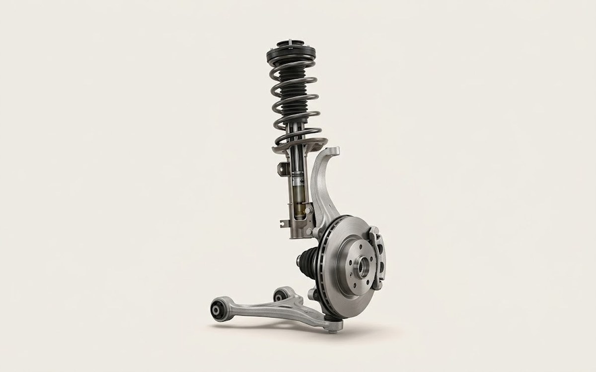 How it works · 3D
How Car Suspension Works
How the part you're working on actually works — in plain English, on a 3D model.
Open in 3D →