Autopapyrus · DAF XF 106 MX-13 390 (2016)
https://autopapyrus.com/guides/daf/xf/engine-overhaul/
https://autopapyrus.com/guides/daf/xf/engine-overhaul/
Compiled automatically from service literature and owner experience. Specs are for the typical configuration — check them against your exact car before you start.
DAF XF 106 MX-13 390 (2016): Engine Overhaul
An overhaul of the 12.9-liter inline six-cylinder PACCAR MX-13 turbodiesel rated at 390 kW includes full disassembly, inspection, boring the block to an oversize (if necessary) or installing replacement liners, replacing the piston assemblies, main and connecting rod bearings and valve stem seals, grinding the crankshaft (if the journals are worn), repairing or replacing the cylinder head, assembly with exact torque values and tightening sequences, and break-in on a test bench or in the vehicle. The engine has a 130 mm bore, 162 mm stroke, 17.5:1 compression ratio and a dry weight of about 1180 kg.
Part
- 🔩 PACCAR MX-13 overhaul kit (pistons PC1976615 STD 130.0 mm with rings and 55 mm wrist pins, cylinder liners PC1843244 with fire ring, main bearing shells PC2047654 STD, connecting rod bearing shells PC1655712 STD Euro 6, thrust washers PC1736755 STD, cylinder head gasket set PC2140884 with valve stem seals). You may also need: crankshaft (if journal wear exceeds the repair size), camshaft, tappets, cylinder head (if cracked or warped), M18 cylinder head bolts (must be replaced), connecting rod bolts (must be replaced), oil pan gasket PC1925946, oil and fuel filters
Step by step
38 steps- Remove the engine from the truck frame: disconnect the negative battery terminal, drain the coolant and oil, remove the turbocharger, downpipe, intercooler, EGR cooler, high-pressure fuel lines and wiring (injectors, pressure and temperature sensors), then remove the transmission or clutch. Attach the engine to the lifting beam, unbolt the engine mounts and lift out the powertrain.
- Clean the outside of the engine with a pressure washer and mount it on an engine stand or pallet.
- Remove the accessories: alternator, starter, air compressor, power steering pump, high-pressure Common Rail fuel pump, oil and fuel filters, sensors and lines.
- Remove the intake and exhaust manifolds, thermostat housing and water pump.
- Remove the cylinder head: loosen the M18 head bolts in the reverse of the tightening sequence (from the edges toward the center), lift off the head with the gasket, and inspect the combustion chambers for carbon buildup, cracks and burned valves.
- Inspect the cylinder head: measure the sealing surface flatness (tolerance no more than 0.05 mm over 300 mm length), and check the valve seats, valve guides for wear and valve springs for tension. If there are cracks in the combustion chamber or between the valve seats, replace the head. If it is warped, resurface it (maximum material removal 0.3-0.5 mm).
- Disassemble the cylinder head: remove the rocker arms and rocker shaft, take out the tappets (label them by cylinder), compress the valve springs with a spring compressor to remove the keepers, then remove the valves, springs and valve stem seals. Lap the valves or replace them if the valve face is worn, and replace the valve guides if clearance exceeds 0.1 mm.
- Install new valve stem seals: slip the seals onto the valve stems through the guide sleeve and seat them fully with light taps on the driver (use moderate force so you do not damage the rubber part).
- Remove the oil pan and oil pump, remove the timing drive cover (chain or gear train), then remove the camshaft and crankshaft sprockets and the chain or gears.
- Remove the main bearing caps. The cap bolts are angle-tightened, so loosen them in the reverse sequence (from the edges toward the center). Remove the bearing shells and mark the caps by cylinder number.
- Lift the crankshaft out of the block and inspect the journals for scoring, out-of-roundness and taper. Measure the main and rod journal diameters with a micrometer (main journal nominal about 90-95 mm, rod journal 75-80 mm; use the exact values from the manufacturer's technical documentation). If wear exceeds 0.05 mm or there is scoring, grind the crankshaft to an undersize of 0.25/0.50/0.75/1.0 mm and fit matching undersize bearing shells.
- Remove the connecting rod bolts and take off the rod caps with the rod bearing shells (the rod bolts are angle-tightened, so loosen them evenly). Push the pistons with the rods up and out through the cylinder bores (first remove the carbon ridge from the top edge of the cylinder so you do not damage the rings and piston).
- Disassemble the piston assemblies: remove the wrist pin circlips, press the pin out of the piston and rod with a press or puller (55 mm floating-type pin), and remove the piston rings with a ring expander (2 compression rings, 1 oil control ring).
- Inspect the cylinder block: measure the cylinder diameter with a bore gauge at three levels (top, middle, bottom) and in two directions (lengthwise and crosswise). The nominal cylinder diameter is 130.0 mm. Out-of-roundness and taper must not exceed 0.03-0.05 mm. If cylinder wall wear exceeds 0.1 mm or there is scoring, bore the block to an oversize of +0.5 mm or +1.0 mm and fit oversize pistons and rings, or install replacement liners (wet type PC1843244 with fire ring).
- Bore the cylinder block on a boring machine (if required): set the block on the machine table, clamp it, and bore all cylinders to the same oversize, keeping the cylinder axis perpendicular to the block deck, with a surface finish of Ra 0.2-0.4 µm. Finish by honing to create a crosshatch pattern (45-60 degree angle) that helps the rings seat and retains oil.
- Wash the block after boring and honing: use hot water with detergent, blow out all oil passages with compressed air, and wipe the cylinder walls with a lint-free rag soaked in engine oil until all abrasive particles are removed.
- Press in the replacement liners (if you chose this repair method): clean the seats in the block, fit new seals on the liners, and press the liners in until they stop using a driver or press (press force 5-10 metric tons). Check the liner protrusion above the block deck (it must be within 0.03-0.08 mm to ensure the head gasket seals properly). Do the final honing of the liner bores.
- Install new main bearing shells in the block and caps: wipe the bearing seats with a clean rag, place the upper shells (with the oil hole) in the block and the lower shells in the caps, and align the locating tabs with the notches in the seats. Lubricate the shells with engine oil.
- Install the thrust washers (PC1736755 STD) on the center main journal (usually the 3rd or 4th support). Fit them on both sides of the crankshaft flange with the working side facing the thrust surfaces of the shaft. Crankshaft end play must be 0.10-0.25 mm (check with a feeler gauge after installation).
- Lay the crankshaft in the block on the main bearing shells and check that it turns freely by hand. Lubricate the journals and shells with clean engine oil.
- Install the main bearing caps according to the markings (cylinder number, direction arrow) and tighten the cap bolts from the center toward the ends in three stages: stage 1: 70 N·m (52 lb-ft), stage 2: 250 N·m (184 lb-ft), stage 3: an additional 150 degrees. Check that the crankshaft turns freely after each tightening stage (if the shaft seizes, there is an assembly error or the shells or journals are damaged).
- Assemble the piston assemblies: fit new piston rings on the pistons (bottom oil control ring, middle compression ring, top compression ring) and position the ring gaps 120 degrees apart. Insert the 55 mm wrist pin through the piston and rod and secure it with circlips on both sides (the circlips must seat fully in the grooves).
- Install the rod bearing shells in the rods and rod caps (PC1655712 STD) and lubricate them with engine oil. Mark the rods by cylinder number.
- Install the pistons with rods into the cylinders: compress the piston rings with a ring compressor (compression band), orient the mark on the piston (arrow or the word FRONT) toward the front of the engine, and insert the piston into the cylinder by lightly tapping the piston crown with a hammer handle. Lower the piston until the rod contacts the crankshaft rod journal.
- Install the rod caps according to the markings and tighten the rod bolts in two stages: stage 1: 50 N·m (37 lb-ft), stage 2: 130 N·m (96 lb-ft), stage 3: an additional 90 degrees. The rod bolts are single-use (angle tightening stretches the bolt to its yield point), so use only new bolts.
- Turn the crankshaft by hand several times to make sure it does not bind and turns freely. Check the crankshaft end play with a feeler gauge (0.10-0.25 mm).
- Install the oil pump and the timing drive chain or gears, align the marks on the crankshaft and camshaft sprockets (set cylinder 1 to TDC on the compression stroke), and fit the timing drive cover with a new gasket.
- Assemble the cylinder head: install the valves with new valve stem seals into the guides, fit the valve springs, and install the keepers. Install the tappets, rocker shaft and rocker arms. Check the valve clearances (adjust according to the manufacturer's specification, usually on a cold engine intake 0.40 mm, exhaust 0.60 mm; use the exact values from the service documentation).
- Clean the block deck and cylinder head surface of any remaining old gasket material with a plastic scraper (not a metal one, to avoid scratching the surface), then degrease the surfaces.
- Place the new head gasket from kit PC2140884 on the block (the gasket has a specific orientation: the UP or TOP marks face up, and the holes must line up with the cylinders).
- Set the cylinder head on the block, insert the new M18 head bolts (the bolts are single-use), and tighten them in four stages following the tightening sequence (from the center toward the ends, in a crisscross pattern): stage 1: 70 N·m (52 lb-ft), stage 2: 250 N·m (184 lb-ft), stage 3: an additional 90 degrees, stage 4: another 90 degrees (180 degrees total after the main tightening).
- Install the intake and exhaust manifolds with new gaskets, the water pump, the thermostat and the accessories (alternator, starter, compressor, high-pressure fuel pump).
- Install the oil pan with a new gasket PC1925946 and tighten the mounting bolts evenly (torque 20-25 N·m (15-18 lb-ft)).
- Fill with engine oil (the lubrication system capacity is about 38-40 liters (40-42 qt) for the MX-13; check the exact volume in the owner's manual) and install a new oil filter.
- Install the engine in the truck frame in the reverse order of removal: secure it on the mounts, connect the transmission, fuel lines, wiring, cooling system, turbocharger, intercooler and downpipe.
- Fill with coolant (the cooling system capacity is about 35-40 liters (37-42 qt)) and bleed the air from the system.
- Perform the first engine start: check the oil pressure (it should rise to 3-4 bar at idle within 10-15 seconds) and check for oil, coolant and fuel leaks. Warm the engine up to operating temperature of 80-90 degrees and listen for unusual noises (knocking, grinding).
- Break in the engine: during the first 500 km of operation, do not exceed 2/3 of maximum engine speed (up to 1200 rpm), avoid hard acceleration and prolonged running at one steady load, and vary the load. After 500 km, change the oil and oil filter (to remove break-in wear products), check the head bolt tightness (apply an additional turn if necessary) and adjust the valve clearances.
Common mistakes and warnings
- Overhauling the MX-13 truck diesel requires specialized equipment (boring machine, honing machine, press, torque wrench with angle gauge, precision measuring tools) and experience with heavy-duty engines. The cylinder head and connecting rod bolts are tightened by the angle method (torque-to-yield) and are single-use. Reusing old bolts will cause the joint to fail and destroy the engine. Failing to follow the torque values, tightening sequence or assembly cleanliness will lead to oil and coolant leaks, blow-by, bearing failure, cylinder scoring and an expensive repeat repair. If you lack the experience and equipment, take the engine to a specialized heavy-duty diesel repair shop.
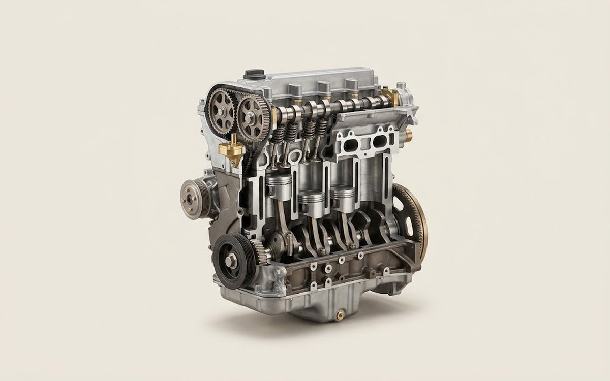 How it works · 3D
How a Car Engine Works
How the part you're working on actually works — in plain English, on a 3D model.
Open in 3D →