Autopapyrus · Ford Sierra 2.0 OHC (1989)
https://autopapyrus.com/guides/ford/sierra/complete-engine-overhaul/
https://autopapyrus.com/guides/ford/sierra/complete-engine-overhaul/
Compiled automatically from service literature and owner experience. Specs are for the typical configuration — check them against your exact car before you start.
Ford Sierra 2.0 OHC (1989): Complete Engine Overhaul
The 2.0 OHC engine (the "Pinto" family) has a cast iron block and an aluminum cylinder head with a single overhead camshaft driven by a toothed belt. An overhaul that includes boring the block and replacing the pistons, bearings and valve stem seals is done with a full teardown, careful measuring and selection of oversizes. Check all clearances and dimensions with a micrometer and bore gauge, not by eye.
Parts
15| № | Part | Genuine part no. |
|---|---|---|
| 01 | Piston set with rings, oversize | 6171407 |
| 6171405 | ||
| 02 | Main and connecting rod bearing set (standard or undersize)size depends on journal grinding results | 1546734 |
| 6131973 | ||
| 03 | Crankshaft thrust washers | 6018218 |
| 6033895 | ||
| 6033896 | ||
| 04 | Engine gasket set (including head gasket) | 5028468 |
| 5028466 | ||
| 5027042 | ||
| 05 | Cylinder head bolt setbolts are single-use | 6157105 |
| 06 | Valve stem seals | 1474550 |
| 1525251 | ||
| 1596529 | ||
| 07 | Front crankshaft seal | |
| 08 | Rear crankshaft seal | |
| 09 | Timing belt | 6139911 |
| 10 | Timing belt idler pulley | 1496915 |
| 11 | Timing belt tensioner | 1496915 |
| 12 | Oil pump or oil pump repair kit | 1438157 |
| 0543572 | ||
| 1451908 | ||
| 13 | Oil filter | 1119421 |
| 5003559 | ||
| 14 | Engine oil, semi-synthetic/synthetic, API SG or higher | |
| 15 | Coolant |
Part numbers are from the manufacturer's original catalogue. Check them against your VIN before ordering.
Tools
13- socket and wrench set
- torque wrench (20-120 N·m (15-89 lb-ft))
- angle gauge or angle-torque protractor
- pulley puller
- engine hoist or overhead crane
- engine stand
- piston ring expander/remover
- piston ring compressor
- bore gauge and micrometers
- valve spring compressor
- valve stem seal remover/installer
- gasket scraper
- Plastigage (calibrated plastic gauging strip for measuring clearances)
Step by step
15 steps- Preparation. Disconnect the battery, drain the oil and coolant, and remove the hood (optional, for convenience), radiator, air filter, carburetor or single-point injection/fuel injection with all related components, drive belts, alternator, water pump, fuel lines and exhaust manifold. Label and photograph all connectors, hoses and cables.
- Engine removal. Disconnect the transmission (or remove the engine together with the transmission, whichever is more convenient), the exhaust system, wires and linkages. Hang the engine from the hoist and lift it out forward and up. Mount it on the stand.
- Timing drive and cylinder head disassembly. Remove the timing belt cover and belt, the camshaft pulley and the valve cover. Set the No. 1 piston to TDC and note the marks. Loosen the cylinder head bolts evenly, working from the edges toward the center, in the reverse of the tightening sequence. Remove the head (if necessary, tap the lugs with a mallet; do not pry at the mating surface).
- Valves and seals. Remove the camshaft and the followers/rocker arms (number them in installation order). Use the spring compressor to remove the springs and keepers, take out the valves and store them in a numbered rack. Replace the valve stem seals with new ones for the 2.0 OHC. Check the valve guides for play, and the valve seats and valve faces: if worn, have the guides replaced and the seats lapped/ground at a machine shop. Check the cylinder head surface with a straightedge and feeler gauge; if it is warped, have it resurfaced. Lap the valves.
- Bottom end disassembly. Turn the block over and remove the oil pan, oil pump, the oil pump drive (depending on version), the flywheel (mark the bolts) and the rear seal. Number the connecting rods and caps and note the marks. Push the pistons out upward, after first removing the carbon deposits/ridge at the top of the cylinders. Remove the main bearing caps and lift out the crankshaft.
- Inspection. Measure the cylinders with a bore gauge at three levels and in two planes (taper and out-of-round). The nominal cylinder diameter of the 2.0 OHC is about 90.8 mm; oversizes are usually +0.25, +0.5, +0.75 and +1.0 mm. Choose the exact size based on the piston set you bought. Measure the crankshaft main and rod journals with a micrometer: if worn or scored, have them ground for undersize bearings (done by a machine shop). Check the block mating surfaces for cracks and flatness.
- Boring and honing. Take the block to a machine shop together with the new pistons. The boring is done to the actual piston size, allowing for the installation clearance specified by the piston manufacturer. Honing (cross-hatch finish) is essential for ring break-in. After machining, wash the block thoroughly with detergent and brushes, blow out the oil passages, and coat the cylinders with oil to prevent rust.
- Bottom end assembly. Wipe the journals, install the main bearing shells in the block saddles and the caps (the tabs must align with the grooves; lubricate the bearings with clean oil). Lay in the crankshaft and check the clearance with Plastigage. Tighten the caps in 2-3 stages. Main cap torque is roughly 80-100 N·m (59-74 lb-ft) (check the exact value in the manufacturer's specification). Check the crankshaft end play (at the thrust washers); it should be within a few tenths of a millimeter. Make sure the crankshaft turns freely.
- Pistons and connecting rods. Stagger the ring gaps at about 120° from each other (not on the wrist pin axis and not toward the thrust side), lubricate the rings and piston with oil, and install them into the cylinder with the ring compressor, with the piston marks (arrow/notch) facing forward, toward the timing belt. Install the rod bearing shells and check the clearance with Plastigage. Rod cap torque is roughly 35-50 N·m (26-37 lb-ft) (exact value per the specification for your bolts; for angle-torque bolts, turn them the specified additional angle). Turn the crankshaft by hand: it should rotate without binding.
- Oil pump, oil pan and flywheel. Install new front and rear crankshaft seals, the pump (fill the pump housing with oil before installation so it primes immediately), the oil pickup screen, and the oil pan with a new gasket. Tighten the oil pan bolts evenly with low torque (a few N·m), without overtightening. Tighten the flywheel with a torque wrench (roughly 70-80 N·m (52-59 lb-ft)) using thread locker.
- Cylinder head installation. Clean the block and head surfaces and make sure the bolt holes are clean and dry (no oil or coolant in the holes). Lay the new gasket the correct way up (marked "TOP"/"FRONT") and place the head on the dowels. Tighten the new bolts strictly in sequence from the center outward, in several stages (usually 2-3 torque passes plus an angle turn) according to the sequence for this engine. Do not reuse the old bolts.
- Camshaft and timing drive. Install the camshaft and adjust the valve train clearances according to the specification (set by the marks). Align the marks on the crankshaft pulley, camshaft pulley and the oil pump/distributor drive. Fit the new timing belt and set the tension correctly, then turn the crankshaft 2 revolutions and recheck the marks. Install the valve cover with a new gasket and tighten the bolts with low torque (a few N·m).
- Ancillaries and installation in the car. Install the manifolds with new gaskets, the water pump, alternator, belts and thermostat. Lower the engine into the engine bay, then connect the transmission and all connectors according to your labels.
- First start. Fill with oil (about 3.5 L (3.7 qt) with the filter) and coolant. Before starting, crank the engine with the starter with the ignition/fuel supply disabled until oil pressure builds (the warning light goes out). Start the engine and keep the speed below 2500-3000 rpm for the first 10-15 minutes. Check for leaks, temperature and oil pressure.
- Break-in. For the first 1000-1500 km, do not load the engine: no hard acceleration, no prolonged driving at constant high rpm and no towing. After 500-1000 km, change the oil and oil filter (the oil will contain metal break-in dust), and retighten the cylinder head and check the valve clearances, if this is required for the type of bolts and gasket used.
Common mistakes and warnings
- This is a difficult job that requires precise measurements and a machine shop for boring and grinding
- If you lack experience, leave the boring, honing and crankshaft grinding to a professional engine shop
- Torque values in this guide are given as ranges; check the exact values for your engine variant in the manufacturer's specification before final tightening
- Do not leave the engine on the stand unsupported, and keep everything clean during assembly, because any abrasive dust in the clearances shortens the life of the overhaul many times over
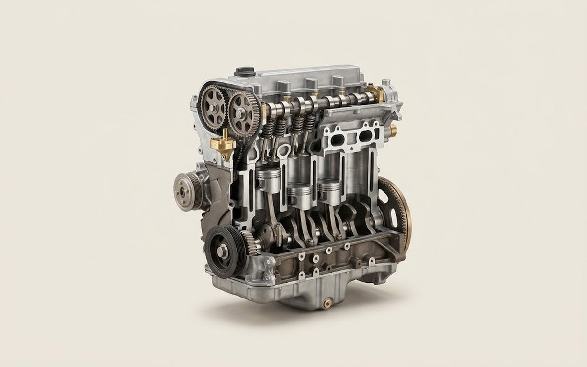 How it works · 3D
How a Car Engine Works
How the part you're working on actually works — in plain English, on a 3D model.
Open in 3D →