Autopapyrus · Jeep Grand Cherokee 3.7 V6 PowerTech (2007)
https://autopapyrus.com/guides/jeep/grand-cherokee/cylinder-head-assembly/
https://autopapyrus.com/guides/jeep/grand-cherokee/cylinder-head-assembly/
Compiled automatically from service literature and owner experience. Specs are for the typical configuration — check them against your exact car before you start.
Jeep Grand Cherokee 3.7 V6 PowerTech (2007): Cylinder Head Assembly
The 3.7 V6 PowerTech is a single overhead cam (SOHC) engine with a chain-driven valvetrain, roller rocker arms and hydraulic lash adjusters. Head assembly consists of preparing the mating surfaces, installing the gasket, tightening the head bolts in several stages with a final angle turn, then installing the rocker arms, chain, camshaft and the accessories. The head bolt torque values below are approximate. Verify the exact values and the tightening sequence against the manufacturer's service manual.
Key figures
- Camshaft sprocket bolt torque122 N·m (90 lb-ft) - step 8, always use the special wrench
- Valve cover bolt torque12 N·m (8.9 lb-ft) - step 9, to avoid damaging the gasket
- Exhaust manifold to head torque25 N·m (18 lb-ft) - step 10, from the center outward
- Intake manifold torque12 N·m (8.9 lb-ft) - step 11
- Throttle body torque7 N·m (5.2 lb-ft) - step 11, do not exceed, the throttle body will be damaged
Check these values against the manufacturer’s specification for your vehicle before you start.
Parts
7| № | Part | Alternatives |
|---|---|---|
| 01 | Cylinder head gasket set for 3.7 V6 (multi-layer steel head gasket) | AlternativesFel-ProVictor ReinzMopar |
| 02 | Cylinder head bolts (set, new) | |
| 03 | Valve cover gasketif cut or deformed | AlternativesFel-ProVictor ReinzMopar |
| 04 | Exhaust manifold gaskets (graphite, perforated) | AlternativesFel-ProVictor ReinzMopar |
| 05 | Intake manifold gasket | AlternativesFel-ProVictor ReinzMopar |
| 06 | Engine oilfor refilling | |
| 07 | Coolantfor refilling |
Tools
11- 10-100 N·m torque wrench
- sockets and ratchet
- angle-torque gauge (torque angle meter)
- rocker arm remover/installer (special tool that compresses the valve spring)
- camshaft holding tool
- timing chain tensioner locking pin
- camshaft sprocket wrench with adapters
- straightedge for checking flatness
- clean rags
- engine oil
- non-abrasive gasket surface cleaner
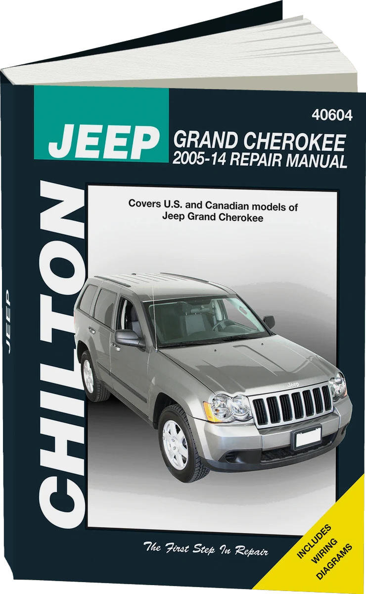 There's a full repair manual for this car
Every system, wiring diagrams and torque specs — not just this job. Chilton and 6 more.
See manuals →
Step by step
13 steps- Disconnect the negative battery cable, drain the coolant and relieve the fuel system pressure. Remove the air intake duct with the resonator, the intake manifold, the valve cover, the exhaust manifold and the timing chain, as far as needed to access the head. Take photos of the chain and camshaft timing marks.
- Check the head for flatness with a straightedge and feeler gauge along its length and diagonally. Inspect the valve seats and guides, the hydraulic lash adjuster bores and the camshaft supports. Do not assemble a warped or cracked head. Send it out for machining (resurfacing) or replace it.
- Thoroughly clean the head and block mating surfaces of any gasket residue with a plastic or wooden scraper, taking care not to scratch the aluminum. Do not let debris or dirt get into the oil and coolant passages or the bolt holes. Blow out the bolt holes in the block with compressed air and remove any fluid left in them.
- Place the new head gasket dry, without sealant, onto the block dowels with the marking facing up (as indicated on the gasket). Lower the head straight down, without shifting the gasket.
- Coat the threads and the underside of the heads of the new bolts with a thin layer of engine oil and thread all the bolts in by hand. Treat the head bolts as single-use: do not reuse old bolts that were tightened with an angle turn.
- Tighten the head bolts with a torque wrench in the correct sequence, working from the center outward in a spiral, in several passes: first a preliminary torque, then an intermediate torque, then a final angle turn of the specified number of degrees. Torque values and sequences differ between reference sources (variants include 30 N·m (22 lb-ft) + 90° and a three-stage tightening with a final 90° turn), so take the exact figures from the manufacturer's specification for your head and model year. Complete each pass fully, without skipping bolts and without stopping halfway around the pattern.
- Lubricate the rocker arms with engine oil and install them with the concave socket seated on the hydraulic lash adjuster, compressing the valve spring with the special remover/installer. Crankshaft position for each cylinder: rocker arms of cylinder 4 - cylinder 1 at BDC on the intake stroke; cylinder 1 - cylinder 1 at BDC on the power stroke; cylinders 3 and 5 - cylinder 1 at TDC on the exhaust stroke; cylinders 2 and 6 - cylinder 1 at TDC on the firing stroke. This is so the valves are not under load.
- Install the camshaft and sprocket, aligning the sprocket pin with the slot. Wipe excess oil off the sprocket bolt (excess oil can lead to overtightening and bolt breakage), thread the bolt in by hand, remove the chain locking pin and tighten the sprocket bolt with the special wrench to 122 N·m (90 lb-ft). Check the timing marks and turn the crankshaft by hand through two full revolutions without binding.
- Install the camshaft position sensor, then the valve cover: clean the mating surfaces; a gasket with no cuts, tears or deformation can be reused. Tighten the valve cover bolts and studs to 12 N·m (8.9 lb-ft). Connect the injectors, the harness retainers and the left-side breather.
- Install the exhaust manifold with a new graphite gasket, tightening from the center outward to 25 N·m (18 lb-ft). Do not overtighten the heat shield nuts, to avoid deforming the shield. Tighten the downpipe to the manifold to 34 N·m (25 lb-ft).
- Install the intake manifold with a new gasket and tighten the bolts to 12 N·m (8.9 lb-ft). Tighten the throttle body to 7 N·m (5.2 lb-ft) (a higher torque will damage the throttle body).
- Install the spark plugs, coils, resonator and air intake duct, and reconnect the battery. Refill the coolant, bleed the air from the system, and change the oil and oil filter if the oil has mixed with coolant.
- Start the engine and let it warm up to operating temperature. Check for oil and coolant leaks, for hydraulic lash adjuster tapping (brief tapping is possible during the first few minutes), and for fault codes in the engine control unit memory. After a few days, check the coolant and oil levels.
Common mistakes and warnings
- The head bolt torque values, the tightening sequence and whether the bolts may be re-tightened are critically important: a mistake leads to a blown gasket and a warped head
- If you have no experience working on engines, have a repair shop install the head
- Work only on a cold engine
- Before starting, make sure there is no fluid in the bolt wells in the block