Autopapyrus · Nissan Murano (2nd generation, Z51)
https://autopapyrus.com/guides/nissan/murano/front-subframe-replacement/
https://autopapyrus.com/guides/nissan/murano/front-subframe-replacement/
Compiled automatically from service literature and owner experience. Specs are for the typical configuration — check them against your exact car before you start.
Nissan Murano (2nd generation, Z51): Front Subframe Replacement
The Murano Z51 subframe carries the lower control arms, the stabilizer bar, the steering rack and, on some versions, the powertrain mounts. Replace it after impact deformation, corrosion or failure of the mounting points. The job is labor-intensive: the subframe is removed together with its components or after they are disconnected, and the engine must be supported while you work. Exact torque values and the sequence for this generation are not documented in publicly available service materials, so the steps below describe the general principle. Check the final torque values against the manufacturer's service manual.
Part
- 🔩 front suspension subframe assembly (Nissan, OE). Subframe fasteners are best replaced with new ones. These include the subframe mounting bolts and self-locking nuts. Check the subframe and control arm bushings separately. If they are worn, replace them separately from the subframe
 There's a full repair manual for this car
Every system, wiring diagrams and torque specs — not just this job. Haynes and 4 more.
See manuals →
Step by step
15 steps- Park the vehicle on a level surface, apply the parking brake and chock the wheels. Disconnect the negative battery terminal. Raise the front of the vehicle on a lift, then remove the front wheels and the lower engine splash shield.
- Remove the front lower plastic shields and air ducts that cover the subframe and block access. If the vehicle has ride height sensors or headlight level sensors, disconnect their links and connectors.
- Disconnect the exhaust brackets and exhaust hangers from the subframe if they are in the way (the front part of the front pipe). Disconnect the wiring connectors and brackets that are attached to the subframe.
- Disconnect the stabilizer bar links from the stabilizer bar itself and, if necessary, remove the stabilizer bar from the subframe. Note the position of the bushings and clamps.
- Disconnect the tie rod ends from the steering knuckles using a separator. Do not strike the threads with a hammer, so you do not damage the stud.
- Disconnect the lower control arms from the steering knuckles: remove the ball joint bolt nuts. Sometimes you need to hold the stud to do this. Press down on the knuckle and release the ball joint from its seat.
- The steering rack is bolted to the subframe. Remove the lower steering shaft joint from the rack, first marking its position relative to the splines. Unbolt the rack and hang it with wire or zip ties, without stretching the hydraulic lines or loading the boots. If the subframe is removed together with the rack, follow the service manual for your trim level.
- On all-wheel-drive versions, disconnect from the subframe any brackets and the driveshaft or differential if they are attached to it. If you have a front-wheel-drive version, skip this step.
- Position a jack stand or hydraulic jack under the subframe. Support the engine from below or above if the powertrain mounts are attached to the subframe. Do not leave the engine hanging on a single mount.
- Mark the outline of the subframe on the body: you will need these marks for reassembly. The position of the subframe relative to the body affects wheel alignment angles.
- Remove the bolts that secure the subframe to the body. While holding the subframe, lower it gradually. Do not let it drop, and do not damage the brake lines, wiring or fuel lines.
- Transfer the components to the new subframe: control arms, stabilizer bar, steering rack, brackets. Replace all worn bushings, boots and mounts with new ones.
- Raise the new subframe into place using the marks and align the mounting holes. Start the fasteners by hand, then tighten them in several passes in a crisscross pattern. Use a torque wrench and the torque specified in the service manual. For bolts of this type it is usually several hundred N·m, but take the exact value from the service manual. Tighten the control arm and stabilizer bar fasteners with the suspension loaded, that is, with the wheels on the ground or with the suspension compressed by a jack under the ball joint.
- Reassemble everything in reverse order: control arms, tie rod ends, steering rack and shaft joint with the marks aligned, stabilizer bar, exhaust, sensors and shields. Install the wheels and tighten the lug nuts in a crisscross pattern. Then lower the vehicle.
- After the replacement, be sure to have a wheel alignment done on an alignment rack. Check that the steering wheel is centered when driving straight and that there are no warning lights on the instrument panel. After 100-200 km, recheck the tightness of the main fasteners.
Common mistakes and warnings
- The subframe is a load-bearing component, and safety and handling depend on it. Work only with the engine and the subframe securely supported. If you have no experience removing subframes and working on suspension, leave the job to a repair shop. Do not use a bent or welded subframe, and do not reuse the mounting bolts if the service manual requires replacing them.
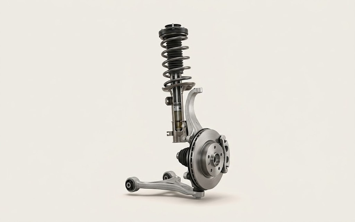 How it works · 3D
How Car Suspension Works
How the part you're working on actually works — in plain English, on a 3D model.
Open in 3D →