Autopapyrus · Suzuki Baleno 1.3 (G13BB, 2001)
https://autopapyrus.com/guides/suzuki/baleno/5-speed-manual-transmission-overhaul/
https://autopapyrus.com/guides/suzuki/baleno/5-speed-manual-transmission-overhaul/
Compiled automatically from service literature and owner experience. Specs are for the typical configuration — check them against your exact car before you start.
Suzuki Baleno 1.3 (G13BB, 2001): 5-Speed Manual Transmission Overhaul
The Baleno transmission with the G13BB engine is a front-wheel-drive 5-speed with a shared case housing the final drive and differential. The case is made of two halves (left and right). The job includes removing the transmission, disassembling the shafts, inspecting parts, replacing bearings, synchronizers and seals, and reassembling with clearance checks. The torque values and wear limits below are approximate. Check the exact values in the manufacturer's service manual for your model version.
Parts
8| № | Part | Genuine part no. | Alternatives |
|---|---|---|---|
| 01 | Input shaft, output shaft and differential bearing set | AlternativesSKFNTNSNR | |
| 02 | Synchronizers (rings, sleeves, springs, detent keys) | 24432-60B20 | |
| 24432-84041 | |||
| 24410-63B20 | |||
| 24472-60B00 | |||
| 03 | Drive axle seals | 09283-40028 | |
| 04 | Shift shaft seal | 09280-11002 | |
| 05 | Snap rings | ||
| 06 | Case gasket or sealant | ||
| 07 | Manual transmission fluid | ||
| 08 | Clutch kit (disc, pressure plate, release bearing)if the disc and pressure plate are worn | AlternativesSachs |
Part numbers are from the manufacturer's original catalogue. Check them against your VIN before ordering.
Tools
12- socket and wrench set
- torque wrench
- bearing puller
- press
- snap ring pliers (expanding)
- punches
- soft drift
- micrometer and caliper
- dial indicator
- lift or pit
- transmission jack
- oil drain pan
 There's a full repair manual for this car
Every system, wiring diagrams and torque specs — not just this job. Haynes AutoFix (online).
See manuals →
Step by step
20 steps- Preparation. Put the car on a lift or over a pit and disconnect the negative battery terminal. Drain the transmission fluid through the drain plug, then clean the plug after draining.
- Remove the air filter with its ducts, the battery with its tray, the starter, the shift cables or linkage, the clutch cable or line, the speed sensor wire, and the reverse light switch wires.
- Remove the engine undercover. Disconnect both tie rods and the lower control arms from the steering knuckles. Pull the drive axles out of the transmission (the splines come out of the side gears with some force) and hang them on wire, making sure the inner CV joints are not bent too far.
- Support the engine from above and the transmission from below with a transmission jack. Remove the bolts that hold the transmission to the engine and the transmission mount (note the length and location of each bolt). Then carefully move the transmission back along the axis of the input shaft so the shaft does not put load on the clutch disc, and lower it down.
- Clean and wash the outside of the transmission. Place it on a stand or workbench. Remove the clutch fork and release bearing, then remove the reverse switch and the speedometer drive or speed sensor.
- Open the case: remove the fifth gear cover and undo the case fasteners. Separate the case halves by prying evenly at the cast-in pry points, without driving wedges into the mating surface. Mark the position of all bolts of different lengths.
- Remove the fifth gear assembly: the snap ring, the synchronizer hub, the 5th gear and the fork. Remember the assembly order and the position of the parts, and take photos at every stage.
- Take the shift shaft and forks out of the case, then lift out the input and output shafts together as an assembly. Remove the differential as an assembly.
- Disassemble the shafts on a clean workbench using a press and puller, laying out the parts in the order you remove them. Replace snap rings and washers with new ones.
- Inspection: replace the tapered roller bearings and roller bearings of the shafts if there is any noise, play, or pitting on the races. Replace synchronizers if the rings are badly worn, the sleeve teeth are chipped, the detent balls do not hold, or the springs are worn. Check the gear teeth, the shaft journals, the shift forks (wear where they contact the sleeve), the differential bearings and the pinion gears. Check the wear limits for each pair in the manufacturer's service manual.
- Check the clearance between the synchronizer ring and the face of the gear. As a guide, when you press the ring onto the gear cone, there should be a noticeable gap, not a tight fit. Use the service manual for the limit value.
- Shaft assembly: press in new bearings with a soft drift, pushing on the outer race (on the shaft, push on the inner race), and lubricate the parts with transmission fluid. Install the gears, synchronizers and snap rings strictly in the reverse order of disassembly. Orient the synchronizer hubs by their marks.
- Replace the drive axle seals and the shift shaft seal, and lubricate their lips. Install the differential, shafts and forks in the case. Check that the shafts turn freely and that each gear engages crisply by hand.
- Apply a thin layer of case sealant (oil-resistant, made for transmission cases) to the case mating surface. Join the case halves and tighten the bolts in a crisscross pattern in several passes to the torque in the service manual, approximately 20-30 N·m (15-22 lb-ft) for M8 bolts.
- Install the fifth gear assembly. Check for smooth rotation and shaft end play, then install the outer covers, sensors and plugs. Tighten the fasteners to the service manual values. For the drain plug and the fill plug, approximately 20-50 N·m (15-37 lb-ft), use the manual's value, and apply sealant to the plug threads if needed.
- Inspect the clutch: if the disc, pressure plate or release bearing is worn, replace them now while the transmission is out. Apply a thin layer of high-temperature grease to the input shaft splines.
- Install the transmission: align it with the engine without putting load on the input shaft. Tighten the transmission-to-engine bolts and the transmission mounts. Use the service manual torque values, approximately 40-60 N·m (30-44 lb-ft) for the main bolts to the engine block, and the manual's values for the mounts.
- Reinstall the drive axles, lower control arms and tie rods, tightening them to the service manual torques with the suspension loaded as the manual specifies (wheels on the ground or the suspension supported). Reconnect the cables, sensors, starter and battery.
- Fill with transmission fluid of the viscosity and grade the manufacturer recommends for this transmission (usually GL-4 for a manual transmission), up to the lower edge of the fill hole with the car level. Use the service manual for the exact capacity.
- Test: with the car on the lift and the engine idling, select every gear and check that there are no leaks from the case and seals. Then take a test drive: listen for noise in each gear, and check that shifting is crisp and that the transmission does not jump out of gear. After 500-1,000 km, check the fluid level and look for leaks again.
Common mistakes and warnings
- This is a complex job
- It requires a press, pullers and experience assembling units with a shared case
- If you lack the experience, it is better to leave the disassembly to a specialist shop
- Support the engine and transmission securely, and never work under a car that is held up only by a jack
- The torque values and wear limits in this guide are approximate
- Before reassembly, check the exact values in the manufacturer's service manual for your vehicle
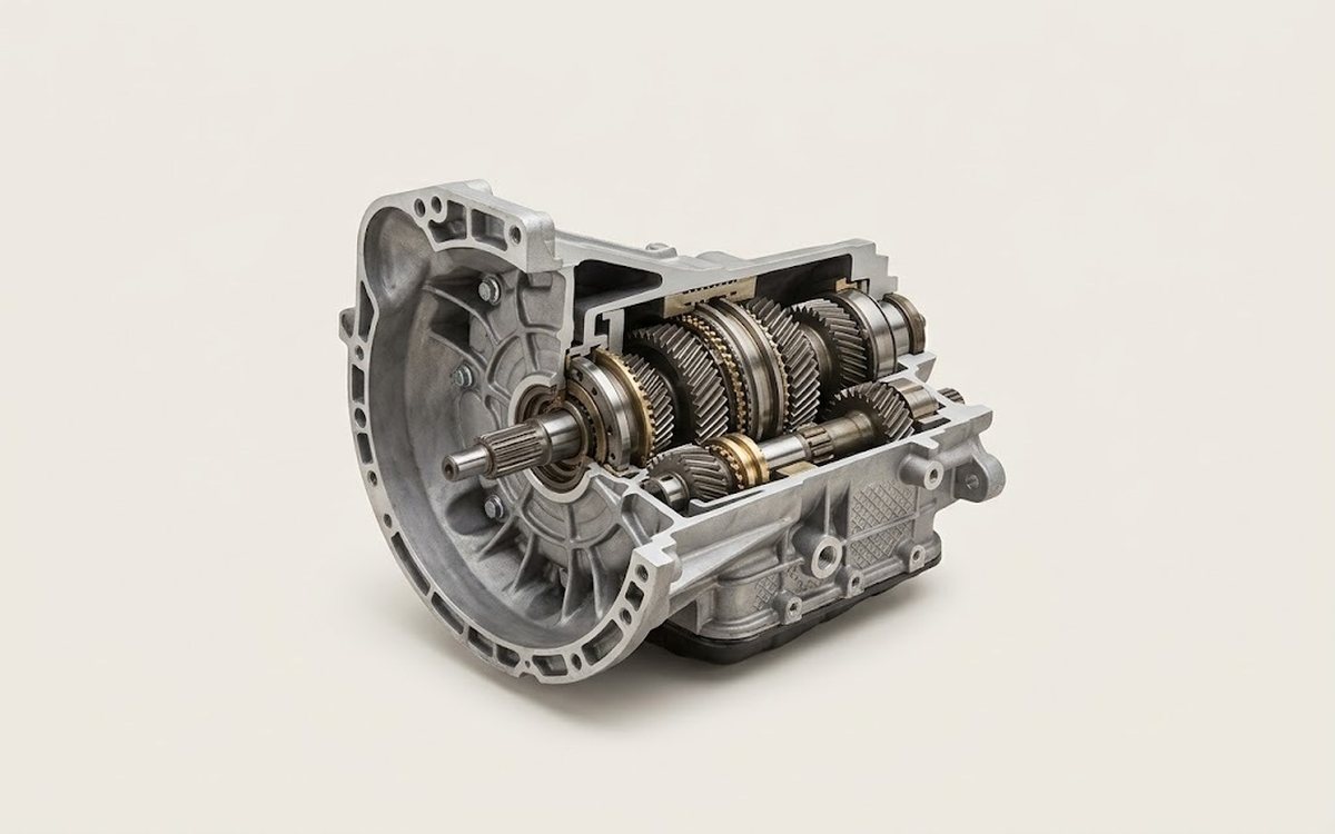 How it works · 3D
How a Manual Transmission Works
How the part you're working on actually works — in plain English, on a 3D model.
Open in 3D →