Autopapyrus · 1UZ-FE Engine Overhaul
https://autopapyrus.com/guides/toyota/land-cruiser-prado/cylinder-boring-pistons-bearings-valve-stem-seals/
https://autopapyrus.com/guides/toyota/land-cruiser-prado/cylinder-boring-pistons-bearings-valve-stem-seals/
Compiled automatically from service literature and owner experience. Specs are for the typical configuration — check them against your exact car before you start.
1UZ-FE Engine Overhaul: Cylinder Boring, Pistons, Bearings, Valve Stem Seals
The 1UZ-FE is a 4.0-liter V8 with a displacement of 3969 cc, four valves per cylinder (32 valves) and a timing belt. The nominal bore is 87.5 mm. The overhaul includes removing the engine, complete disassembly, inspection of the block and cylinder heads, boring and honing the cylinders for oversize pistons, and replacing the bearings and valve stem seals. Critical dimensions (clearances, oversize steps) must be determined by measurement, not by eye. If the engine is being installed in a Land Cruiser Prado J90 as a replacement for the original engine, keep in mind that the accessories and mounts may differ from the factory ones.
Parts
18| № | Part | Genuine part no. | Alternatives |
|---|---|---|---|
| 01 | Piston setoversize determined by measuring the block | Riken, Taiho, Toyota Genuine, Nippon Piston | |
| 02 | Piston ring set | Riken, Taiho, Toyota Genuine, Nippon Piston | |
| 03 | Main bearingsstandard or undersize for a reground crankshaft | Riken, Taiho, Toyota Genuine, Nippon Piston | |
| 04 | Rod bearingsstandard or undersize for a reground crankshaft | 13408-62060 | Riken, Taiho, Toyota Genuine, Nippon Piston |
| 05 | Valve stem seals (set)for 32 valves | Riken, Taiho, Toyota Genuine, Nippon Piston | |
| 06 | Full engine gasket set | Riken, Taiho, Toyota Genuine, Nippon Piston | |
| 07 | Exhaust manifold gaskets | 17173-62050 | Riken, Taiho, Toyota Genuine, Nippon Piston |
| 08 | Timing belt | Riken, Taiho, Toyota Genuine, Nippon Piston | |
| 09 | Timing belt tensioner pulley | 19000-62292 | Riken, Taiho, Toyota Genuine, Nippon Piston |
| 19000-62440 | |||
| 10 | Timing belt idler pulley | Riken, Taiho, Toyota Genuine, Nippon Piston | |
| 11 | Water pump | 16100-69395 | Riken, Taiho, Toyota Genuine, Nippon Piston |
| 16100-69396 | |||
| 12 | Thermostat | Riken, Taiho, Toyota Genuine, Nippon Piston | |
| 13 | Front crankshaft seal | Riken, Taiho, Toyota Genuine, Nippon Piston | |
| 14 | Rear crankshaft seal | Riken, Taiho, Toyota Genuine, Nippon Piston | |
| 15 | Camshaft seals | Riken, Taiho, Toyota Genuine, Nippon Piston | |
| 16 | Oil filter | ||
| 17 | Coolant | ||
| 18 | Engine oil, API SL/SM |
Part numbers are from the manufacturer's original catalogue. Check them against your VIN before ordering.
Tools
13- Engine hoist (crane)
- engine stand
- socket and ratchet set
- torque wrench (up to 120 N·m (88 lb-ft))
- angle gauge for torque-angle tightening
- bore gauge and micrometers
- Plastigage or feeler gauge
- pulley puller
- oil seal driver
- valve spring compressor
- piston ring compressor
- honing head (at the machine shop)
- soft drift for piston removal
Step by step
22 steps- Preparation. Drain the oil and coolant, and disconnect the negative battery terminal. Remove the hood, radiator grille, radiator, fan with shroud, and the air duct with the mass airflow (MAF) sensor. Relieve the pressure in the fuel rail and disconnect the fuel hoses. Label all connectors and vacuum hoses.
- Remove the accessories: alternator, A/C compressor (do not open the refrigerant circuit; just unbolt it and move it aside), power steering pump, and drive belts. Disconnect the driveshafts and the exhaust downpipes. Remove the transmission together with the transfer case, or separate the transfer case from the engine.
- Engine removal. Support the engine with the hoist, unbolt the engine mounts, separate the engine from the transmission, and lift it out. Mount it on the engine stand. Keep all fasteners sorted into groups.
- Disassembly. Remove the intake manifold with the throttle body and injectors, the ignition coils and spark plugs, the valve covers on both banks, the crankshaft pulley, and the timing belt covers. Set the timing marks (cylinder 1 piston at TDC), photograph the position of the marks, then remove the timing belt, camshaft pulleys, idler pulleys, and the water pump.
- Remove the camshafts, following the loosening sequence for the bearing caps (evenly, from the ends toward the center, in several passes). Label the caps and keep them in order. Lay out the lifters (if shim-type, as a set) by cylinder and valve.
- Remove the cylinder heads. Loosen the bolts evenly in several passes, in the reverse of the tightening order (from the outside toward the center). Do not pry the head apart with a screwdriver between the mating surfaces; use only the pry points provided in the casting.
- Remove the oil pan, oil pickup tube, and oil pump. Before removing the connecting rod caps, mark the rods and caps by cylinder. Unbolt the rod caps and push the pistons out upward through the cylinders (from the top), after first removing the carbon ridge at the top of the cylinders.
- Crankshaft. Loosen the main bearing cap bolts in several passes, remove the caps (mark their order and direction), and lift out the crankshaft. Lay out the upper and lower bearing shells in order so you can assess wear.
- Block cleaning and inspection. Wash the block thoroughly, clean the oil passages with brushes, and blow them out with compressed air. Check the head mating surface with a straightedge and feeler gauge, and inspect the cylinders for scoring. Measure the cylinders with a bore gauge at three levels and in two planes. The nominal diameter is 87.5 mm; taper and out-of-round beyond the specified limit are grounds for boring. If the block has cracks or deep scoring, the repair is not worthwhile.
- Boring and honing. Take the block to the machine shop together with the new pistons (boring is done precisely to the actual piston size, allowing for the piston-to-cylinder clearance, usually about 0.02-0.05 mm; use the exact value from the specifications). Honing with the correct crosshatch angle (about 45-60°) is mandatory. After boring, wash the block with hot water and detergent, then dry it and coat it with oil to prevent corrosion.
- Crankshaft. Measure the journals with a micrometer: main journals are nominally about 67.0 mm, rod journals about 52.0 mm. If wear or out-of-round exceeds the limit, have the crankshaft ground to the undersize bearing size. Check shaft runout, the oil passages, and the seal seating surfaces.
- Cylinder head inspection. Check the surface for warpage, inspect the valve seats and valve guides, and measure the guide clearance and the condition of the valve stems. If necessary, lap the valves, replace the valve guides, and recut the seats. Clearances and allowable warpage are per the specifications.
- Valve stem seals. Compress the valve springs, remove the keepers, springs, and old seals. Install the new seals on the guides with a driver, lightly lubricated with oil. Be careful not to damage the seal lip; slide it onto the valve stem without tilting, and never reuse the old seals. Reassemble the valves and tap the end of each valve stem with a plastic hammer to seat the keepers.
- Pistons and rings. Measure the ring end gaps in the cylinder (insert the ring squarely into the cylinder) and check the side clearance in the grooves. Install the rings with the end gaps positioned per the manufacturer's diagram (gaps spread around the circumference, not in a line, and not opposite the wrist pin hole). Be sure to follow the "top" markings on the rings. Pistons must be matched by weight and size.
- Crankshaft installation. Wipe the bearing seats and bearing shells, install the shells (locating tabs go into the notches), lubricate them with engine oil or special assembly lube, and lay in the crankshaft. Check the end play with a feeler gauge. Tighten the main caps in the order given in the specifications. Guideline: main bolts — 27 N·m (20 lb-ft), then an additional 90° (the side bolts of the caps are tightened separately; confirm the values in the specifications). After tightening, the crankshaft should turn smoothly by hand without binding. Check the bearing clearance with Plastigage.
- Piston installation. Lubricate the cylinders and pistons with engine oil and, using a ring compressor, insert the pistons (the mark on the piston crown faces forward, toward the front of the vehicle; the direction is given in the specifications). Fit the rod caps according to the marks. Guideline for rod bolt tightening: 25 N·m (18 lb-ft), then an additional 90°. Torque-to-angle rod bolts are best replaced with new ones. Check that the crankshaft turns freely after each piston.
- Install the oil pump, new front and rear crankshaft seals, oil pickup tube, and oil pan with sealant (per the specifications, applied in a thin, even layer). Tighten the oil pan bolts in several passes at low torque (approximately 5-10 N·m (44-89 lb-in) for the small bolts).
- Cylinder head installation. Clean the mating surfaces and install new head gaskets, strictly following the direction marks. Tighten the head bolts in several passes, in order from the center outward, followed by an angle tightening. Use the exact values (torque and angles) for the 1UZ-FE from the specifications; torque-to-angle bolts should preferably be replaced with new ones. Then install the camshafts and valve cover gaskets, and be sure to check the valve clearances.
- Timing. Set the crankshaft and camshaft marks per the specifications, and install the new idler pulleys, water pump, and timing belt. Turn the crankshaft 2 revolutions by hand and recheck that the marks line up. If the marks do not line up, repeat the installation. A timing error causes the valves to hit the pistons.
- Accessories and reinstallation. Install the intake and exhaust manifolds with new gaskets, the spark plugs, coils, injectors (with new O-rings), and the accessories. Put the engine back in place, connect it to the transmission, and reconnect all connectors and hoses according to your labels.
- Filling and starting. Add fresh oil, replace the oil filter, and fill with coolant, bleeding out any air pockets. Before the first start, crank the engine with the starter with the ignition disabled (remove the fuel pump fuse or the coil fuse) until oil pressure appears. Start the engine and let it idle, monitoring oil pressure, checking for leaks, and watching the temperature.
- Break-in. For the first 1000-1500 km, avoid hard loads, prolonged driving at maximum rpm, and heavy towing. Change the oil and filter after the first 500-1000 km, then follow the regular maintenance schedule. After about 1000 km, recheck for leaks.
Common mistakes and warnings
- This is a difficult job that requires precise measurements and special tools: an error in clearances, valve timing, or tightening torques will lead to another engine failure
- Boring, honing, and crankshaft grinding must be done only at a specialized machine shop
- If you have no experience with engine overhauls, have a professional engine builder do the assembly
- Always check the tightening values marked "per the specifications" against the 1UZ-FE service manual
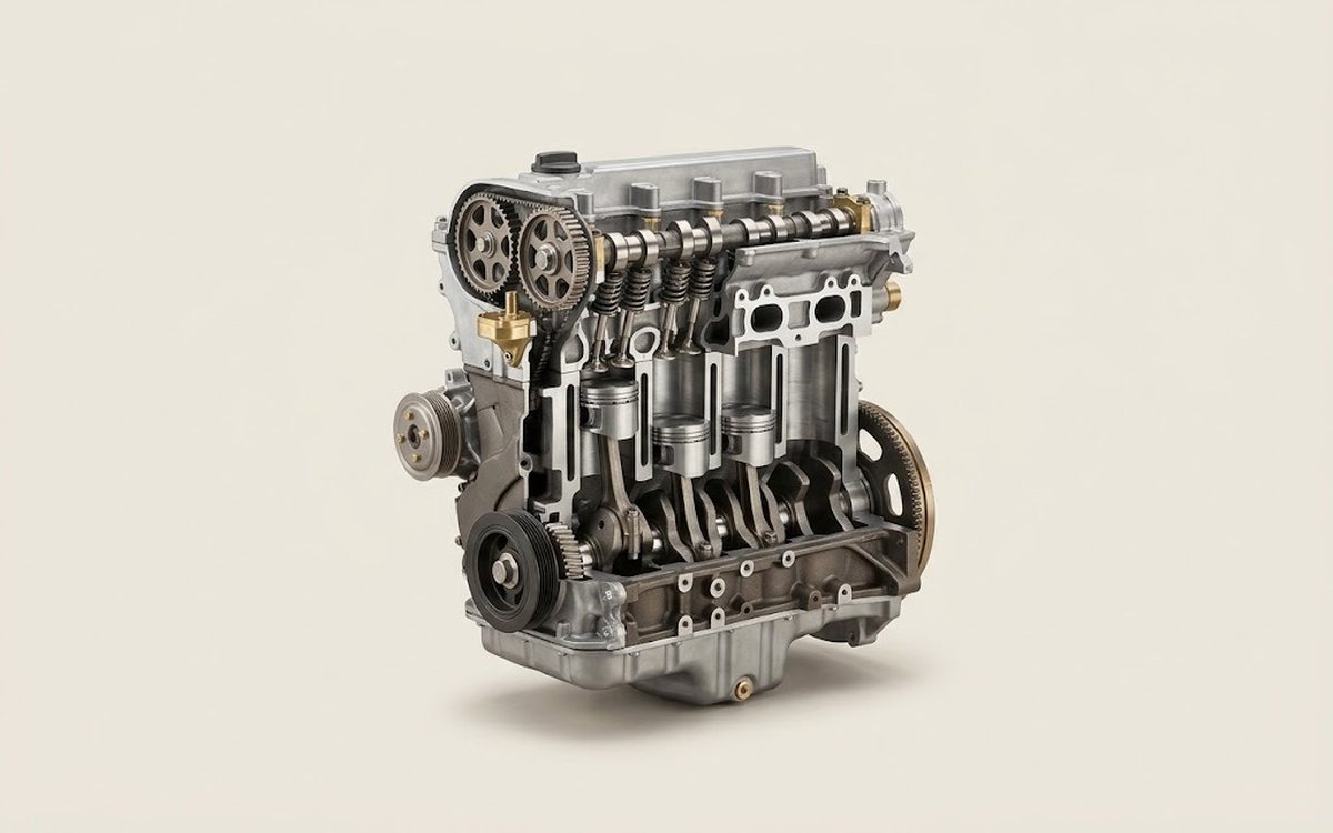 How it works · 3D
How a Car Engine Works
How the part you're working on actually works — in plain English, on a 3D model.
Open in 3D →