Autopapyrus · BMW X5 (F15) 2015
https://autopapyrus.com/catalog/bmw/x5/guides/front-brake-rotor-replacement/
https://autopapyrus.com/catalog/bmw/x5/guides/front-brake-rotor-replacement/
Compiled automatically from service literature and owner experience. Specs are for the typical configuration — check them against your exact car before you start.
BMW X5 (F15) 2015: Front Brake Rotor Replacement
Front rotors are replaced as a pair, together with the pads. The front caliper is a floating, single-piston design, and the front wheels have no electronic parking brake, so no service mode is needed. Work on one side at a time. This guide covers the front axle only; the rear axle is different, with the parking brake drum shoes inside the rotor hat. The torque values below are only partly confirmed by two sources, so check them against the manufacturer's specifications.
Key figures
- Caliper carrier bolt torque110 N·m (81 lb-ft), with a torque wrench and E18 socket in step 15 (verify the value against the manufacturer's specifications, as one source gives a different torque with an angle turn)
- Caliper guide pin torque30 N·m (22 lb-ft), 7 mm hex bit, step 18
Check these values against the manufacturer’s specification for your vehicle before you start.
Parts
5| № | Part | Alternatives |
|---|---|---|
| 01 | Front brake rotors, ventedpairFind on Amazon → | AlternativesBremboATEZimmermannTextarBosch |
| 02 | Front brake padsaxle setFind on Amazon → | AlternativesBremboATEZimmermannTextarBosch |
| 03 | Left front pad wear sensorif neededFind on Amazon → | |
| 04 | Rotor retaining screwsFind on Amazon → | |
| 05 | Caliper carrier boltsif the manufacturer requires replacementFind on Amazon → |
Amazon links search by the part name; use Amazon's fit check for your car before ordering. We may earn a commission from qualifying purchases.
Tools
11- jack and jack stands Amazon →
- 17 mm lug wrench Amazon →
- E18 Torx socket (external Torx) Amazon →
- 6 mm and 7 mm hex bits with a ratchet Amazon →
- torque wrench Amazon →
- screwdriver Amazon →
- wire brush Amazon →
- brake cleaner Amazon →
- C-clamp or piston retractor tool Amazon →
- hammer Amazon →
- ceramic brake grease Amazon →
 There's a full repair manual for this car
Every system, wiring diagrams and torque specs — not just this job. Haynes AutoFix (online) and 3 more.
See manuals →
Step by step
25 steps · 5 stagesStage 1 of 5 Preparation 3 steps
- Park the vehicle on level ground, loosen the 17 mm lug bolts half a turn, then raise the front of the vehicle and set it on jack stands.
- Remove the wheel. Inspect the rotor: a deep wear lip, cracks, or blue blotchy heat discoloration are all reasons to replace it. Check the minimum thickness on the rotor edge (MIN TH stamp).
- Turn the steering wheel away from the wheel you are working on to open up access to the caliper.
Stage 2 of 5 Caliper removal 7 steps
- Use a 6 mm hex bit to remove the rotor retaining screw (the small screw on the hub). Seat the bit fully so you don't strip the socket.
- Remove the anti-rattle spring clip: push the lower edge away from the hub, then pry the upper edge with a screwdriver and lift it off the caliper.
- Remove the guide pin caps and use a 7 mm hex bit to remove both guide pins.
- Lift the caliper off the rotor and hang it from a piece of wire, a zip tie, or a bungee cord. Never let it hang from the brake hose.
- On the left front wheel, disconnect the wear sensor wire from the inner pad.
- Remove the pads from the carrier.
- Using the E18 socket, remove the two caliper carrier bolts (hold the carrier with a second tool if needed) and take off the carrier.
Stage 3 of 5 Rotor replacement 4 steps
- Remove the old rotor. If it is stuck, tap on its face with a hammer (not on the hub or the bearing).
- Clean the hub mounting surface with a wire brush down to bare metal. Any dirt will cause runout and vibration under braking.
- Wipe the new rotor with brake cleaner, since it is coated with preservative oil. Fit it on the hub and secure it with the retaining screw using a 6 mm hex bit. Tighten the screw to roughly 10-16 N·m (7-12 lb-ft); check the exact value in the manufacturer's specifications.
- Clean the caliper carrier with a wire brush and brake cleaner, especially the pad contact surfaces.
Stage 4 of 5 Reassembly 6 steps
- Install the carrier on the steering knuckle. Thread both bolts in by hand, then tighten them with the E18 socket to 110 N·m (81 lb-ft) (per one source; another gives 165 N·m (122 lb-ft) plus an additional angle turn, so verify the value and whether the bolts must be replaced in the manufacturer's specifications).
- Apply a thin layer of ceramic grease to the ears and edges of the outer pad (not the friction surface) and insert it in the carrier. Insert the inner pad into the caliper by pressing its spring clips into the piston.
- Compress the caliper piston with a C-clamp or retractor tool until it bottoms out, otherwise the caliper will not fit over the new, thicker rotor. Watch the fluid level in the reservoir, as it will rise. If necessary, remove the excess fluid with a syringe.
- Fit the caliper over the rotor and carrier. Tighten the guide pins with a 7 mm hex bit to 30 N·m (22 lb-ft) (per one of the sources; check against the manufacturer's specifications). Install the caps.
- Install the anti-rattle clip: first hook its tabs under the caliper carrier, then press from the hub toward the caliper.
- On the left wheel, connect the wear sensor wire to the new inner pad. If the sensor was replaced, trace the wire to the connector box on the inside of the fender, disconnect the old connector, plug in the new one, and secure the wire in its clips.
Stage 5 of 5 Finishing and checks 5 steps
- Repeat steps 2-20 on the other wheel.
- Install the wheels, thread the bolts in by hand in a star pattern, lower the vehicle, and tighten the lug bolts with a torque wrench to the manufacturer's specification (for the F15, around 140 N·m (103 lb-ft)).
- Before driving, pump the brake pedal several times until it feels firm, so the pistons seat against the pads. Check the brake fluid level in the reservoir and top it up to the MAX mark with DOT 4 fluid if needed.
- Reset the brake service interval in the instrument cluster menu if the indicator came on or the wear sensor was replaced.
- Bed in the new rotors: 8-10 brake applications from 60-80 km/h down to 20-30 km/h without coming to a full stop, then let the brakes cool. Avoid hard stops for the first 200-300 km.
Common mistakes and warnings
- Brakes are a safety system
- If you have no experience, leave the job to a repair shop
- Do not let the caliper hang from the hose, do not touch the friction surfaces of the rotors and pads with your hands, and do not drive until you have pumped the pedal to a firm feel
- Replace rotors and pads only as a pair on the axle
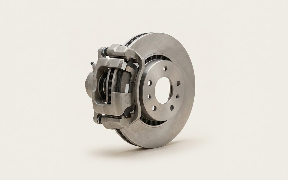 How it works · 3D
How Car Brakes Work
How the part you're working on actually works — in plain English, on a 3D model.
Open in 3D →
Spotted a mistake? Tell us →
Our articles
 Brand stories
The History of BMW
BMW AG stands for Bayerische Motoren Werke, or "Bavarian Motor Works." BMW is a major manufacturer of cars, engines…
Read →
 Garage
Fuel Quality Indicators: What Octane and Cetane Numbers Mean
What is an octane number? What about a cetane number? Which fuel should you choose for a high-compression engine?…
Read →
 Before you buy
How to Pick Up Your Car from the Dealership the Right Way
If you've decided to buy a car from a dealership, it isn't enough to simply choose a model you like, pay for it, and…
Read →