https://autopapyrus.com/catalog/lexus/es/guides/front-lower-control-arm-removal-and-installation/
Lexus ES 350 (2GR-FE) (2013): Front Lower Control Arm Removal and Installation
The 2013 model year is the fifth-generation ES (XV60) with the 3.5 L 2GR-FE engine. The front lower control arm is attached to the subframe by bushings and to the steering knuckle by a ball joint. The ball joint nut and the control arm bolts are tightened firmly, so you will need a good breaker bar. This guide covers replacing a single front lower control arm. Doing the other arm on the same axle is the same job, just on the opposite side.
Parts
4| № | Part | Alternatives |
|---|---|---|
| 01 | Front lower control arm assembly with ball jointleft or rightFind on Amazon → | AlternativesMoogMevotechLemförderTRW |
| 02 | Control arm boltsif worn or corrodedFind on Amazon → | |
| 03 | Cotter pin or self-locking ball joint nutnewFind on Amazon → | |
| 04 | Control arm bushingsif neededFind on Amazon → |
Amazon links search by the part name; use Amazon's fit check for your car before ordering. We may earn a commission from qualifying purchases.
Tools
10- Floor jack and two jack stands Amazon →
- lug wrench Amazon →
- sockets and wrenches 12-22 mm Amazon →
- ratchet and breaker bar with extension Amazon →
- torque wrench Amazon →
- ball joint separator or pry bar Amazon →
- hammer Amazon →
- penetrating oil Amazon →
- marker or paint for alignment marks Amazon →
- second floor jack with a wooden block under the engine if needed Amazon →
Read the codes yourself
A scanner plugged into the OBD2 port under the dashboard shows which fault codes the car has stored, before you buy any parts. Cars sold in the US from 1996, and petrol cars in Europe from 2001 (diesels from 2004), have this port.
- Basic code reader, about $20–40: reads and clears engine codes Amazon →
- Bluetooth scanner with a phone app, about $30–100: live sensor data, and on many cars ABS and airbag codes too Amazon →
Check that the scanner lists your make and model year before you buy. We may earn a commission from qualifying purchases.
 There's a full repair manual for this car
Every system, wiring diagrams and torque specs — not just this job. Haynes and 9 more.
See manuals →
Step by step
26 steps · 5 stagesStage 1 of 5 Preparation 4 steps
- Park the car on level ground, set the parking brake, and chock the rear wheels. Loosen the front wheel lug nuts half a turn.
- Apply penetrating oil to the threads of the ball joint nut, the control arm bolts, and the sway bar link. Let it soak for 10-15 minutes.
- Raise the front of the car, place jack stands at the designated support points under the body, and remove the wheel.
- If the car has a plastic underbody shield or fender liner, remove the sections that block access to the control arm and subframe.
Stage 2 of 5 Removal 8 steps
- Inspect the control arm and take a photo of its position. If there are any eccentric or adjustable parts, mark their position with a marker so the alignment stays close to the original after reassembly.
- Remove the nut from the sway bar link and disconnect the link from the control arm or from the strut. If the link's ball stud spins, hold the stud with a hex key.
- Remove the cotter pin and unscrew the ball joint nut. First loosen it a few threads, but do not remove it completely: the nut should stay on the stud.
- Break the ball joint stud loose from the steering knuckle. A separator works best, but you can strike the knuckle's eye with a hammer. Do not hit the threads of the stud or the boot.
- Fully remove the nut and pull the stud out of the knuckle. Make sure the CV axle boot is not stretched: move the knuckle outward carefully.
- Locate the bolts that attach the control arm to the subframe (front and rear). If the arm is a two-link design, identify which link you are replacing by where the ball joint is located.
- If a bolt hits part of the engine or subframe and will not come out, support the engine with a second jack and a wooden block under the oil pan, and loosen the engine mounts just enough to pull the bolt out. According to owner reports, this is common on the passenger side.
- While holding the control arm with your hand, remove the control arm bolts and take the arm out of the subframe, pulling it slightly down and forward.
Stage 3 of 5 Preparing the new control arm 2 steps
- Compare the new control arm with the old one: side, length, ball joint position, and bushing sleeve locations.
- Wipe the mounting surfaces and the ball joint stud. Clean the bolt threads with a wire brush. Replace any badly worn or rusty bolts.
Stage 4 of 5 Installation 6 steps
- Install the control arm into the subframe, insert the bolts, and tighten them by hand only, not fully.
- Insert the ball joint stud into the knuckle hole and start the nut. You can tighten it fully right away, while the arm is not loaded.
- Tighten the ball joint nut with a torque wrench. The approximate value is 100-140 N·m (74-103 lb-ft); use the exact value from the manufacturer's service manual. If it is a castle nut, tighten it to the nearest slot and install a new cotter pin. If it is self-locking, replace it with a new one.
- Reconnect the sway bar link and tighten its nut (approximately 70-80 N·m (52-59 lb-ft); check the service manual for the exact value).
- Reinstall any engine mounts and brackets you moved, if you removed them. Tighten them to the manufacturer's specification.
- Install the wheel, tighten the lug nuts by hand in a crisscross pattern, and lower the car onto its wheels.
Stage 5 of 5 Final tightening and check 6 steps
- Fully tighten the control arm-to-subframe bolts only with the car lowered onto its wheels, with the suspension under normal load. Otherwise the bushings will be twisted while static and will tear quickly. The approximate torque is 85-120 N·m (63-89 lb-ft) (figures differ between sources, so check the exact value in the manufacturer's service manual).
- Tighten the lug nuts with a torque wrench in a crisscross pattern, approximately 100-105 N·m (74-77 lb-ft) (check the service manual for the exact value).
- Check for play and knocking: rock the wheel by hand up and down and side to side, inspect the ball joint boot, and make sure all cotter pins and nuts are in place.
- Take a test drive of 5-10 km (3-6 miles): check for knocks, vibrations, and any pull to one side in the steering.
- Be sure to get a wheel alignment after replacing the control arm: the wheel geometry changes when the arm is replaced.
- After 100-200 km (60-120 miles), recheck the tightness of the lug nuts and control arm bolts.
Common mistakes and warnings
- Suspension and steering are safety-critical systems
- If you do not have experience or a torque wrench, have a repair shop do the work
- Support the car only on jack stands, and never work under it on a jack alone
- The torque values above are approximate; check the exact values in the manufacturer's service manual
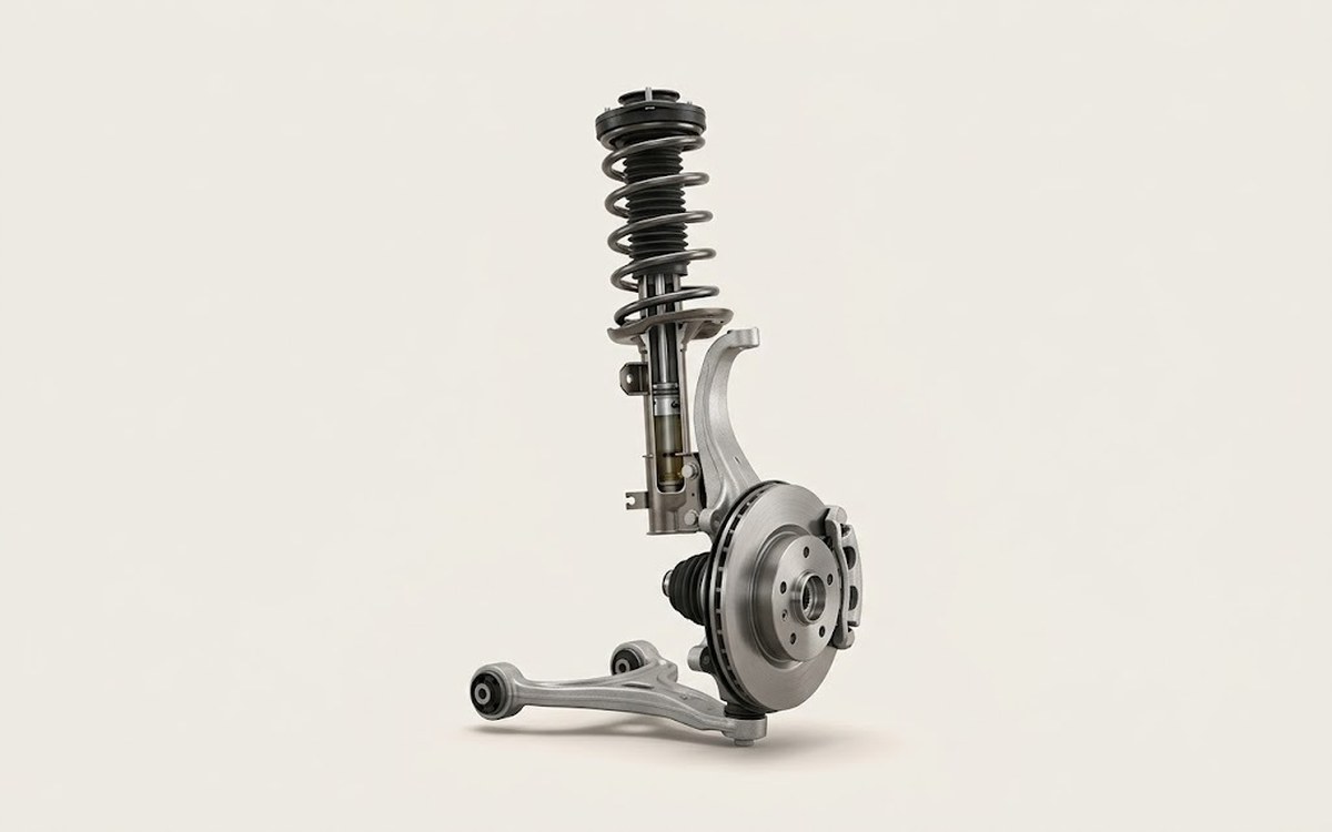 How it works · 3D
How Car Suspension Works
How the part you're working on actually works — in plain English, on a 3D model.
Open in 3D →