https://autopapyrus.com/catalog/skoda/yeti/guides/haldex-coupling-repair-and-replacement-in-the-rear-drive-unit/
Skoda Yeti 4x4 (1st generation): Haldex Coupling Repair and Replacement in the Rear Drive Unit
On the Yeti 4x4, power goes to the rear axle through a Haldex coupling mounted on the rear differential. There is no separate transfer case. Repair comes down to changing the fluid, replacing pump V181, replacing control module J492, or replacing the whole coupling. Never open the pressure accumulator, because it is dangerous. The oil filter inside the coupling is not a scheduled maintenance item.
Key figures
- Driveshaft flange nut tightening210 N·m (155 lb-ft). Always a new nut with thread locker, and a flange holding tool is required (step 14)
- Tightening of the 4 bolts holding the coupling housing to the rear differential50 N·m (37 lb-ft). Use a torque wrench (step 14)
- Control module and pump cover bolt tightening6 N·m (53 lb-in). Low torque, do not overtighten (steps 13-14)
- Fluid inspection plug tightening15 N·m (11 lb-ft). The plug and O-ring are always new, tightened after filling (step 17)
- Exhaust flex section bend limitno more than 10°. Otherwise the flex section will be damaged when the exhaust is lowered (step 3)
Check these values against the manufacturer’s specification for your vehicle before you start.
Diagram: where the Haldex coupling sits under the Yeti and what is next to it
- 1Haldex coupling housing on the rear differential, with cooling fins: the whole job centers here, oil is drained and filled through the plugs.
- 2Coupling control unit: it has an electrical connector on top; disconnect it before removing the coupling.
- 3Pump V181: a cylinder under the coupling; to replace it, remove the pump cover and change the two 34 mm rings.
- 4Propshaft flange with bolts: unbolt the shaft and pull it off strictly horizontally without damaging the seal and centering bushing.
- 5Propshaft: once off the flange, support it with a jack or tie it up; marks on the flex disc and flange must match at assembly.
- 6Exhaust flex section: do not bend it more than 10°, or it will fail.
- 7Heat shield under the propshaft: removed at the start of the job.
Parts
8| № | Part | Genuine part no. |
|---|---|---|
| 01 | Gen 4 Haldex coupling assembly (rear differential 0BR)when replacing the whole couplingFind on Amazon → | |
| 02 | Haldex coupling O-ringswhen repairing the couplingFind on Amazon → | 0BS598301 |
| 0AY598305 | ||
| 02D598275 | ||
| 03 | V181 pump O-rings, 34 mm diameter2 pcsFind on Amazon → | |
| 04 | Rear differential flange sealFind on Amazon → | 02D525596B |
| 05 | Flange nut (new)Find on Amazon → | |
| 06 | Haldex coupling fluid (Skoda/VW specification)Find on Amazon → | |
| 07 | Drain plug with O-ringnewFind on Amazon → | N90813202 |
| 08 | Inspection plug with O-ringnewFind on Amazon → | N10037105 |
Amazon links search by the part name and genuine number; use Amazon's fit check for your car before ordering. We may earn a commission from qualifying purchases.
Part numbers are from the manufacturer's original catalogue. Check them against your VIN before ordering.
Tools
10- lift or inspection pit Amazon →
- jack for the transmission/engine Amazon →
- socket set and ratchet Amazon →
- torque wrench Amazon →
- driveshaft flange holding tool (special tool) Amazon →
- Haldex coupling filling device (VAS 6291 type) Amazon →
- drain pan Amazon →
- wooden wedge about 50 mm Amazon →
- thread locker Amazon →
- paint or marker for alignment marks Amazon →
 There's a full repair manual for this car
Every system, wiring diagrams and torque specs — not just this job. Haynes AutoFix (online).
See manuals →
Step by step
18 steps- Diagnose the fault. Typical symptoms: rear axle slip, AWD control module fault codes, whining or heat near the rear differential, oil leaks. Read the fault codes with a diagnostic scan tool first. If the coupling has simply gone a long time without service, a fluid change is often enough.
- Raise the vehicle on a lift. Place a drain pan under the rear differential.
- Remove the exhaust system near the coupling clamp: unbolt the muffler bracket from the subframe and tie up the front pipe. Do not bend the flex section of the pipe more than 10°, or it will be damaged.
- Remove the heat shield under the driveshaft.
- Remove the torque reaction mount from the transmission: remove the two bolts B and C. Do not loosen bolt A.
- Loosen the driveshaft center support bearing. On the Yeti, remove the heat shield screws first, then thread the support back on so the shaft can be moved.
- Check the marks on the driveshaft flex disc and on the Haldex flange. If there are no marks, make your own: the position must match on reassembly.
- While holding the flange with a counterhold, unbolt the driveshaft from the rear differential flange. You need a helper to move the engine-transmission assembly forward. Insert a wooden wedge about 50 mm thick between the subframe and the transmission.
- Pull the shaft off the centering pin strictly straight, without tilting it. If you damage the centering sleeve or the seal, the shaft will have to be replaced. Support the shaft with a jack or tie it to the exhaust hanger.
- Disconnect the electrical connector of the coupling control module.
- Remove the inspection plug, then the drain plug, and drain all the fluid. Install a new drain plug with a new O-ring. The drain plug tightening torque is not given in the open sources: tighten it to the manufacturer's specification.
- Remove the mounting screws and pull the coupling out of the rear differential. Remove the O-ring from it. Always use a new O-ring on installation and wet it with Haldex fluid.
- If you are replacing pump V181: remove the pump cover and replace both O-rings (34 mm), lubricating them with Haldex fluid. Do not open the filter cover or the pressure accumulator cover.
- Installation. Torque specs for coupling assembly: the 4 bolts holding the coupling housing to the rear differential 50 N·m (37 lb-ft); control module bolts and pump cover bolts 6 N·m (53 lb-in); driveshaft flange nut 210 N·m (155 lb-ft), always a new nut with thread locker. Tighten with a torque wrench. Check the other torque specs (coupling mounting screws, driveshaft bolts, mounts) against the manufacturer's specification.
- Reassemble in reverse order: driveshaft aligned to the marks, center support bearing, torque reaction mount, heat shield, exhaust. Reconnect the connector.
- Filling with fluid: remove the inspection plug and thread in the filling device adapter all the way. Route the hose over the driveshaft without sagging and bring it up above the left rear wheel. Lower the vehicle, open the valve and let the fluid fill the coupling for several minutes. Raise the vehicle again: if fluid flows out of the adapter, the coupling is full. Lower the container below the level of the coupling so the excess drains back, then remove the device. The fluid capacity is approximately 0.85 L (0.90 qt), but go by fluid coming out of the inspection hole.
- Install a new inspection plug with a new O-ring, torque 15 N·m (11 lb-ft).
- Wipe the fluid off the subframe and the surrounding area. Take a test drive, then check for leaks and clear the fault codes with the scan tool. The coupling fluid change interval is approximately 60,000 km (about 37,000 miles) per the schedule; confirm it in the service book.
Common mistakes and warnings
- Never open the Haldex pressure accumulator cover: risk of injury
- This job involves moving the engine-transmission assembly and the driveshaft
- If you lack experience and special tools, leave it to a repair shop
- Use only special Haldex coupling fluid, because ordinary transmission fluid will damage the coupling
- Do not damage the flange seal or the centering sleeve
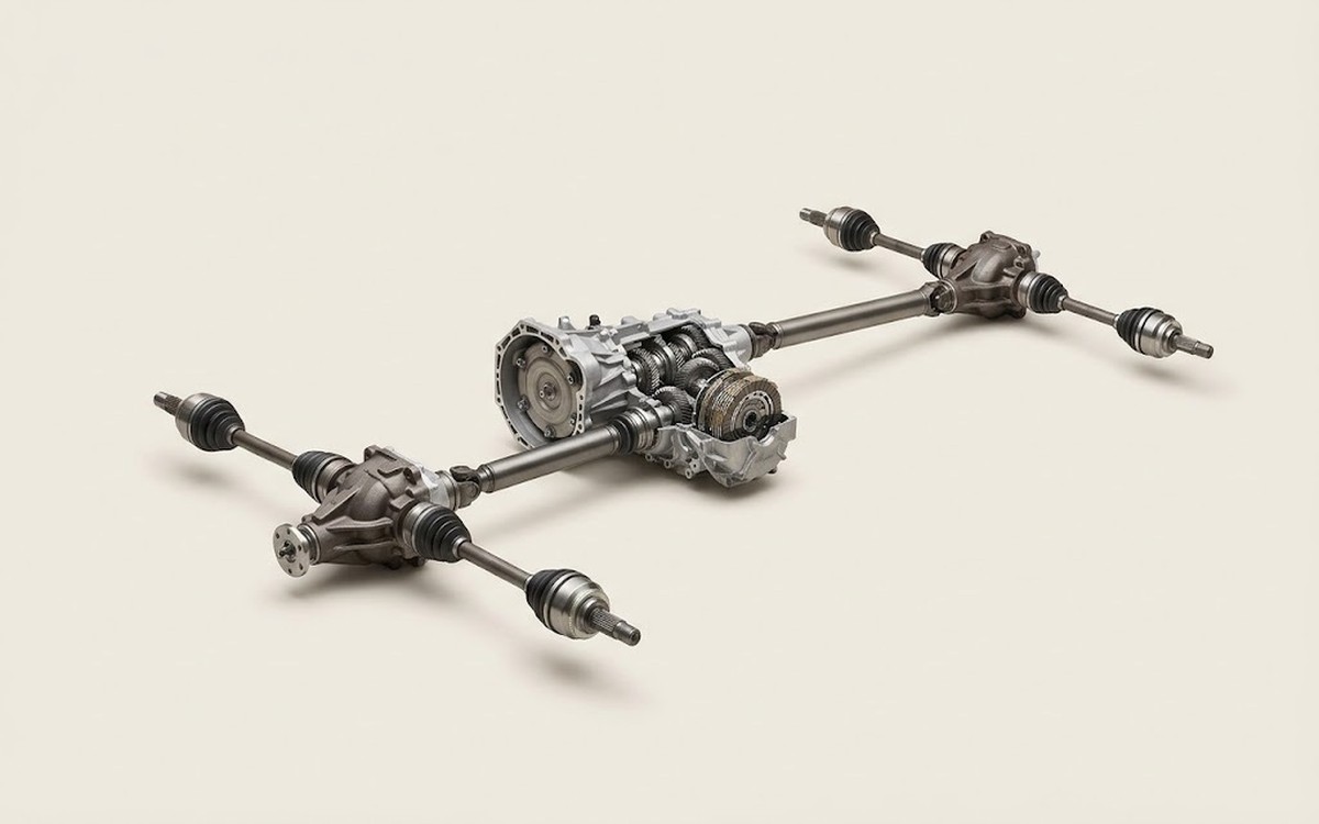 How it works · 3D
How All-Wheel Drive Works
How the part you're working on actually works — in plain English, on a 3D model.
Open in 3D →
Spotted a mistake? Tell us →
Our articles
 Brand stories
The History of Skoda
A detailed look at how the Škoda automotive brand came to be.
Read →
 Garage
Fuel Quality Indicators: What Octane and Cetane Numbers Mean
What is an octane number? What about a cetane number? Which fuel should you choose for a high-compression engine?…
Read →
 Before you buy
How to Pick Up Your Car from the Dealership the Right Way
If you've decided to buy a car from a dealership, it isn't enough to simply choose a model you like, pay for it, and…
Read →