https://autopapyrus.com/catalog/volkswagen/multivan/guides/complete-engine-overhaul/
Volkswagen Multivan T6 2.0 TDI CXHA 150 hp (2017): Engine Overhaul
The CXHA engine belongs to the EA288 family (2.0 TDI, bore 81.0 mm, stroke 95.5 mm) and has a belt-driven timing system. An overhaul includes removing the engine, complete disassembly, inspection of the block, crankshaft and cylinder head, replacement of bearings, rings and gaskets, then assembly and break-in. 2017 vehicles are the T6, and the engine is mounted transversely. For torque values below marked "per factory specification," check the factory service manual for your engine. Values without that note are approximate for the EA288 family.
Key figures
- Cylinder borenominal block size: compare it with the measurement taken during inspection (step 21)81.0 mm
- Permissible cylinder taper for honingif greater, the block is bored (step 21)up to 0.05 mm
- Cylinder head flatness toleranceif exceeded, the head is replaced, not machined (step 21)0.05 mm
- Camshaft sprocket nuttightened with a counter-hold when installing the timing belt (step 32)100 N·m (74 lb-ft)
- Camshaft housing boltsnew bolts, from the center outward (step 29)8 N·m (6 lb-ft) + 90°
Check these values against the manufacturer’s specification for your vehicle before you start.
Diagram: where the valve cover, turbo and oil filter are on the engine
- 1Valve cover with injectors and fuel rail: removed during disassembly; injectors are fitted with new seals on assembly.
- 2Oil filler cap: engine oil 5W-30 goes in here, about 4.7 L with the filter.
- 3Turbo together with the exhaust manifold: removed during disassembly; the turbo oil feed line is filled with oil on installation.
- 4Cooling system reservoir: G13 antifreeze goes in here; bleed air from the system after the first start.
- 5Oil filter: fit a new one on assembly.
- 6Oil dipstick with the yellow handle: used to check the oil level.
Parts
18| № | Part |
|---|---|
| 01 | Engine gasket set with head gasket (multi-layer metal)Find on Amazon → |
| 02 | Cylinder head bolts (single-use, torque-to-yield)setFind on Amazon → |
| 03 | Main and rod bearing shellsstandard or undersize, based on measurementsFind on Amazon → |
| 04 | Piston ring setFind on Amazon → |
| 05 | Oversize pistonsif neededFind on Amazon → |
| 06 | Timing belt kit (belt, tensioner, idler pulley, water pump)Find on Amazon → |
| 07 | Crankshaft pulley bolt (single-use)Find on Amazon → |
| 08 | Connecting rod cap bolts (single-use)setFind on Amazon → |
| 09 | Front crankshaft sealFind on Amazon → |
| 10 | Rear crankshaft sealFind on Amazon → |
| 11 | Valve stem sealssetFind on Amazon → |
| 12 | Oil pan gasket or sealantFind on Amazon → |
| 13 | Oil filterFind on Amazon → |
| 14 | Engine oil 5W-30Find on Amazon → |
| 15 | Coolant G13Find on Amazon → |
| 16 | Injectorsif neededFind on Amazon → |
| 17 | Glow plugsif neededFind on Amazon → |
| 18 | Oil pumpif neededFind on Amazon → |
Amazon links search by the part name; use Amazon's fit check for your car before ordering. We may earn a commission from qualifying purchases.
Tools
16- vehicle lift Amazon →
- engine crane and engine stand Amazon →
- sockets and wrenches 8-19 mm Amazon →
- Torx and XZN (multi-spline) bit set including one for the crankshaft pulley Amazon →
- torque wrenches 5-50 N·m (4-37 lb-ft) and 40-200 N·m (30-148 lb-ft) Amazon →
- angle gauge for torque-angle tightening Amazon →
- micrometer and bore gauge Amazon →
- straightedge and feeler gauges Amazon →
- Plastigage Amazon →
- piston ring pliers and ring compressor Amazon →
- cylinder hone Amazon →
- puller Amazon →
- crankshaft and camshaft locking tools Amazon →
- injection pump pulley locking tool Amazon →
- sprocket counter-hold tools Amazon →
- press for valve guides Amazon →
 There's a full repair manual for this car
Every system, wiring diagrams and torque specs — not just this job. Haynes and 5 more.
See manuals →
Step by step
43 steps · 7 stagesStage 1 of 7 Diagnosis and preparation 5 steps
- Confirm that an overhaul is necessary: compression or cylinder leak-down test, oil consumption, oil pressure, smoke, metal in the oil. If the problem is only in the cylinder head or injectors, an overhaul is not needed.
- Disconnect the negative battery terminal. If the vehicle has a battery with a start-stop system, disconnect it in the proper sequence, waiting for the control modules to shut down.
- Drain the oil and coolant into clean containers. It is best to check the oil for metal shavings at this point.
- Remove the underbody shield, the front panel with the bumper if needed for access, and the front wheels.
- Photograph and label all connectors, hoses and wiring harnesses. High-pressure fuel system: relieve the pressure before disconnecting any lines, and work only in a clean work area.
Stage 2 of 7 Engine removal 7 steps
- Remove the air ducts, the intercooler with its pipes, and the air filter and its housing.
- Disconnect the fuel lines, the injector, sensor and engine harness connectors, and plug any open fittings.
- Remove the drive belt, the A/C compressor (without opening the refrigerant circuit, hang it to the side), and the alternator.
- Disconnect the exhaust system from the turbocharger, and remove the diesel particulate filter and the exhaust aftertreatment components. Remove everything connected with the exhaust sensors carefully and do not drop them.
- Disconnect the driveshafts from the transmission, the tie rods and steering rack, the anti-roll bar, and the lower control arms if you are removing the engine together with the subframe. Tighten the suspension during assembly per factory specification.
- Disconnect the transmission cable or linkage and the clutch (or remove the transmission separately after the engine is out). Position the engine on the crane and remove the mount fasteners.
- Lower the engine with the transmission and subframe downward, or remove it per factory specification. Separate the engine from the transmission and mount the engine on the stand.
Stage 3 of 7 Disassembly and inspection 9 steps
- Remove the intake manifold, the EGR and its pipes, the turbocharger and exhaust manifold, the injectors and glow plugs, and the water pump and cooling system housings.
- Remove the timing belt covers and the crankshaft pulley (the pulley bolt is single-use, XZN socket, lock the crankshaft). Before removing the belt, set the timing to TDC and lock the crankshaft, camshafts and injection pump pulley with the special locking tools.
- Remove the timing belt, the pulleys and the water pump.
- Remove the valve cover and the camshaft housing as a single unit, without disassembling the bearing caps. Remove the camshafts only if necessary and according to the marks.
- Loosen the cylinder head bolts in reverse order (from the edges to the center) and remove the cylinder head, without lifting it by the injector wells. The weight of the complete cylinder head is about 20-25 kg.
- Remove the oil pan, the oil pickup tube and the oil pump, and the bedplate if necessary.
- Mark the connecting rods and caps by cylinder. For connecting rods with fracture-split caps, the cap fits only its own rod and only in its original position. Remove the pistons with the rods upward.
- Remove the main bearing caps, lift out the crankshaft, remove the bearing shells, and note their positions.
- Inspection. Block: check the cylinders for taper and out-of-round. If taper is up to 0.05 mm, hone them. If it is greater, or if there is out-of-round, bore them for an oversize piston (an oversize above +0.5 mm is not advisable). Crankshaft: measure the journals with a micrometer and check the end play. Clearance guidelines for EA288: main bearings 0.03-0.06 mm, rod bearings 0.03-0.05 mm, crankshaft end play 0.07-0.17 mm (verify per factory specification, using Plastigage). Cylinder head: check for flatness, tolerance 0.05 mm. If it is exceeded, replace the head, do not machine it. Pressure-test the cylinder head for cracks, replace the guides and seals, and lap the valves.
Stage 4 of 7 Block assembly 7 steps
- Wash the block thoroughly, blow out the oil passages with compressed air, and install new passage plugs if necessary. Check the piston cooling oil jets.
- Install new bearing shells, lubricate them with engine oil, lay in the crankshaft, and tighten the main bearing caps with new bolts, in several stages from the center outward. Torque and angle per the manufacturer's specification. Check that the crankshaft turns freely.
- Check the ring end gap in the cylinder. Guideline for this diesel: top ring 0.25-0.45 mm, second ring 0.30-0.55 mm, oil control ring 0.25-0.75 mm (verify against the factory specification). Stagger the ring gaps about 120° apart.
- Install the rings on the pistons with the mark facing up, lubricate the cylinders and pistons with oil, compress the rings with the ring compressor, and insert the pistons according to the direction marks.
- Install the rod bearing shells and the caps on their own connecting rods, and tighten them with new bolts per factory specification (torque and angle). Check that the crankshaft turns easily after each rod.
- Install the oil pump, the oil pickup tube, the bedplate if equipped, and the oil pan with sealant. Tighten the oil pan bolts in a crisscross pattern, guideline 10-15 N·m (7-11 lb-ft), per factory specification, and do not start the engine until the sealant has cured according to its instructions.
- Install the new front and rear crankshaft seals, the flywheel or damper, and the clutch, tightening per factory specification.
Stage 5 of 7 Cylinder head and timing installation 6 steps
- Assemble the cylinder head with new valve stem seals, valves, hydraulic lifters and the camshaft housing. The camshaft housing bolts are single-use, tightening 8 N·m (6 lb-ft) + 90°, in order from the center outward.
- Wipe the block and cylinder head surfaces, and fit a new head gasket with the TOP marking facing up, without sealant. Install the cylinder head onto the locating dowels. The pistons must not be at TDC during installation.
- Thread in the new single-use cylinder head bolts (10 pieces), lubricating the threads and the underside of the head as instructed, and tighten from the center outward in several stages with an angle turn at the end. Check the tightening pattern and torque value against the factory specification for the CXHA engine, then perform the 90° turns precisely, without overtightening.
- Install the new pulleys, water pump and timing belt with the crankshaft, camshafts and injection pump locked. Loosen the camshaft and injection pump sprocket nuts, tension the belt per factory specification, and tighten the camshaft sprocket with a counter-hold to 100 N·m (74 lb-ft) (per factory specification).
- Remove all locking tools, turn the crankshaft 2 full revolutions (720°), and insert the locking tools again. If they do not go in, the timing is set incorrectly, so repeat the installation.
- Install the crankshaft pulley with a new bolt, tighten per factory specification (torque plus angle), and fit the belt covers.
Stage 6 of 7 Ancillaries and installation in the vehicle 5 steps
- Install the valve cover, the injectors with new seals, the glow plugs, the fuel lines and the intake manifold with new gaskets.
- Install the turbocharger with new gaskets, pour oil into the turbocharger oil feed line, and connect the oil return line. Install the exhaust manifold and EGR.
- Join the engine to the transmission (center the clutch), install the engine with the subframe back in place, and tighten the mounts, driveshafts, steering and suspension per factory specification.
- Connect all connectors and hoses, and install the exhaust system, intercooler, pipes and drive belt.
- Fill with 5W-30 oil meeting VW 507.00 or 504.00 (guideline about 4.7 L (5.0 qt) with the filter, check the level with the dipstick), a new oil filter, and G13 coolant in the correct ratio.
Stage 7 of 7 First start and break-in 4 steps
- Prime the fuel system, check for leaks, connect the battery, and read and clear fault codes with a diagnostic scan tool.
- Start the engine and let it idle for 1-2 minutes with no load. Check the oil pressure (the warning light goes out) and look and listen for leaks and knocking. Warm it up to operating temperature and bleed the air from the cooling system.
- Check the oil and coolant levels after the engine cools, and retighten anything that requires retightening per factory specification.
- Break-in for the first 1,000 km: no full loads, no long idling or maximum rpm, and accelerate smoothly. After the break-in, change the oil and filter.
Common mistakes and warnings
- All bolts for the cylinder head, connecting rods, main bearing caps, crankshaft pulley and camshaft housing on this engine are single-use and must not be reused
- This job requires special tools, measurements and cleanliness
- If you lack experience and the equipment for honing and measuring, leave it to a repair shop
- In the high-pressure fuel system, injury is possible when pressure is released, so work carefully
- Torque values marked "per factory specification" in the steps must be verified in the factory service manual for the CXHA engine
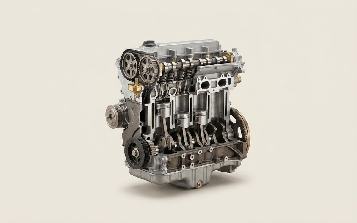 How it works · 3D
How a Car Engine Works
How the part you're working on actually works — in plain English, on a 3D model.
Open in 3D →
Spotted a mistake? Tell us →
Our articles
 Brand stories
The History of Volkswagen
Volkswagen proved to the world that a car can be "the people's car": good-looking, affordable and fun.
Read →
 Garage
Fuel Quality Indicators: What Octane and Cetane Numbers Mean
What is an octane number? What about a cetane number? Which fuel should you choose for a high-compression engine?…
Read →
 Before you buy
How to Pick Up Your Car from the Dealership the Right Way
If you've decided to buy a car from a dealership, it isn't enough to simply choose a model you like, pay for it, and…
Read →