Autopapyrus · Fiat Ducato 2.3 Multijet (2014)
https://autopapyrus.com/guides/fiat/ducato/engine-overhaul/
https://autopapyrus.com/guides/fiat/ducato/engine-overhaul/
Compiled automatically from service literature and owner experience. Specs are for the typical configuration — check them against your exact car before you start.
Fiat Ducato 2.3 Multijet (2014): Engine Overhaul
The F1A-family engine (2.3 L, 4 cylinders, 16 valves, Common Rail) is overhauled with the engine removed from the vehicle. The engine machine shop does the block boring and the crankshaft and cylinder head inspection, so accurate measurements and cleanliness during assembly matter most. Exact torque values and clearances for this version could not be found in publicly available service materials, so the general principles and guidelines are given below. Verify all numeric values against the engine manufacturer's specifications.
Parts
15| № | Part |
|---|---|
| 01 | Piston and ring set (standard or oversize for rebore) |
| 02 | Crankshaft bearing set (main and rod)size according to measurements |
| 03 | Crankshaft thrust washers |
| 04 | Valve stem seals |
| 05 | Full engine gasket set |
| 06 | Cylinder head gasket |
| 07 | Cylinder head bolts |
| 08 | Connecting rod boltssingle-use |
| 09 | Crankshaft pulley boltsingle-use |
| 10 | Timing drive kit (belt/chain, rollers, water pump) |
| 11 | Oil pumpdepending on condition |
| 12 | Crankshaft seals |
| 13 | Engine oil |
| 14 | Oil filter |
| 15 | Coolant |
Tools
14- vehicle lift and engine hoist
- engine stand
- torque wrench (ranges 10-100 N·m (7-74 lb-ft) and 100-300 N·m (74-221 lb-ft))
- angle-tightening gauge
- micrometer and dial bore gauge
- feeler gauges
- Plastigage
- valve spring compressor
- drivers for valve stem seals and crankshaft seals
- camshaft and crankshaft timing locking tools
- socket set and ratchet
- straightedge
- drain pans
- clean rags and a marker for labeling parts
 There's a full repair manual for this car
Every system, wiring diagrams and torque specs — not just this job. Haynes AutoFix (online) and 3 more.
See manuals →
Step by step
16 steps- Preparation. Disconnect the battery and drain the oil and coolant. Remove the skid plate, the bumper and the upper crossmember (depending on the body design), the intercooler and its hoses, and the radiator with the fan. Photograph and label all connectors and hoses.
- Fuel system. Relieve the pressure in the rail (do not start the engine, wait at least 10 minutes). Disconnect the high-pressure fuel lines and cap all openings: even tiny amounts of dirt are unacceptable in a Common Rail system. Store the injectors and the high-pressure pump in clean packaging.
- Engine removal. Disconnect the wiring harnesses, the A/C (remove the compressor without opening the refrigerant circuit), the power steering, the turbocharger lines and the exhaust. Separate the transmission from the engine (or lower the engine together with the transmission, whichever suits your lift), then remove the clutch and flywheel. Support the powertrain with the hoist and lift it out upward or downward, depending on access. The flywheel is a dual-mass type: watch the bolts, as they are single-use.
- Disassembly. Mount the engine on the stand. Remove the turbocharger, the exhaust and intake manifolds, the timing belt or timing drive, the water pump, the cylinder head, the oil pan, the oil pickup tube and the balance shaft unit (if equipped). Before removing the pistons, mark the cylinder number on each connecting rod and cap. Do not mix up the connecting rod caps and main bearing caps.
- Cylinder head inspection. Pressure test the head and check the sealing surface for warping with a straightedge and feeler gauge; the tolerance is in the manufacturer's specifications. Replace the valve stem seals on every valve: remove the spring with a compressor, and with the valves removed, check the stem-to-guide clearance and the valve seat lapping. If necessary, send the head to the machine shop for resurfacing and replacement of the guides and seats.
- Block and crankshaft inspection. Clean the block thoroughly, blow out the oil passages and replace the oil gallery plugs. Measure the cylinders with a bore gauge at several levels and in two planes. If wear or out-of-roundness exceeds the tolerance, or there is scoring, bore the block to the oversize piston size: buy the pistons first, then have the block bored exactly to the piston size with the clearance specified by the manufacturer (the shop works from the finished piston set). After boring, the block must be honed (with a hone of the correct grit) and washed thoroughly with a brush and detergent until a clean white rag comes away clean.
- Crankshaft. Measure the journals with a micrometer at several points and check the runout. Based on the results, decide whether to have it ground for undersize bearings or to keep the standard size. Replace the thrust washers if they are worn.
- Bearing installation. Install the bearing shells dry into dry seats, lubricating only the working surface with clean engine oil. Check the clearance with Plastigage: tighten the caps according to the specification (usually in two or three stages with a final angle turn on the stretch bolts), remove them and measure. Take the torque values for the main and rod bolts strictly from the engine manufacturer's specifications; no range can be given, because these are angle-torque bolts tightened in stages.
- Pistons and rings. Check the ring end gap, install the rings with the TOP marks facing up, and space the gaps 120 degrees apart. Lubricate the rings and cylinders with oil and use a ring compressor. The arrow or mark on the piston crown must face the direction specified by the manufacturer (usually toward the timing belt). Check the piston protrusion above the block surface: it determines the cylinder head gasket thickness (gaskets come in different thicknesses, so choose by measurement).
- Bottom end assembly. Install the crankshaft, the caps, the seals (lubricating the lip), the oil pump, the oil pickup tube with a new gasket, and the oil pan with sealant according to the specification. Turn the crankshaft by hand: it should rotate without binding.
- Cylinder head. Install a new gasket of the correct thickness and new cylinder head bolts. Tightening is done in several stages in a pattern from the center outward (first stage, second stage, angle turn; the exact values are in the engine specifications). Do not reuse old bolts and do not lubricate the threads unless the manufacturer's specification says to.
- Timing. Set the timing marks and lock the shafts with the locking tools. Install the new kit: belt or chain, rollers, tensioner and water pump. Turn the crankshaft two full revolutions by hand and recheck that the marks align. Tension the tensioner according to the specification.
- Ancillary components. Install the manifolds (new gaskets, self-locking nuts), the turbocharger (first pour oil into the oil feed line and spin the turbo to lubricate the bearing), the injectors with new sealing washers and clamps, and the fuel lines, tightening them with a torque wrench to the specification.
- Engine installation. Install a new clutch and the flywheel (dual-mass depending on condition), using new flywheel bolts. Then install the engine in the vehicle by reversing the removal sequence. Fill with coolant, fresh oil of the correct viscosity and approval (per the specification for this engine, usually semi-synthetic or synthetic 5W-30 meeting Fiat 9.55535), and install a new oil filter.
- First start. Crank the engine with the starter without fuel delivery until the oil pressure light comes on and goes out, then start it and let it idle with no load. Check for leaks, pressure and any unusual noises. Warm it up, let it cool, check the fluid levels and retighten the connections.
- Break-in. For the first 1000-1500 km, avoid full loads, prolonged idling and sustained high rpm; vary the engine speed. Change the oil and filter after the break-in (about 1000-3000 km, as recommended by the engine shop), then monitor the level.
Common mistakes and warnings
- Overhauling a modern Common Rail diesel requires cleanliness and precise measurements: a mistake in clearances, tightening or cylinder head gasket thickness selection will lead to another engine failure
- Take the tightening torques for the main, rod and cylinder head bolts, as well as clearances and tolerances, only from the engine manufacturer's specifications; do not guess
- If you have no experience disassembling engines and working with high-pressure fuel systems, leave the removal, assembly and boring to a professional engine machine shop
- After an engine or injector replacement, the control unit may need adaptations, which are performed with a diagnostic scan tool
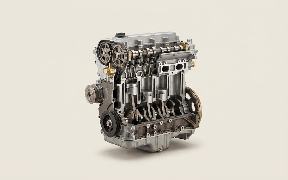 How it works · 3D
How a Car Engine Works
How the part you're working on actually works — in plain English, on a 3D model.
Open in 3D →