Autopapyrus · Mitsubishi Delica 2.5 TD 4D56 (1993)
https://autopapyrus.com/guides/mitsubishi/delica/piston-and-connecting-rod-replacement/
https://autopapyrus.com/guides/mitsubishi/delica/piston-and-connecting-rod-replacement/
Compiled automatically from service literature and owner experience. Specs are for the typical configuration — check them against your exact car before you start.
Mitsubishi Delica 2.5 TD 4D56 (1993): Piston and Connecting Rod Replacement
This job is needed for scored cylinders, a burned piston, broken rings, connecting rod bearing knock, or an engine overhaul. The 4D56 engine has a 91.1 mm bore, 95 mm stroke and a 21:1 compression ratio. The pistons come out through the top of the cylinders, so the cylinder head and oil pan must be removed. The connecting rod bolts on this engine are tightened with an angle turn, so it is best to replace them. Before installing new pistons, the cylinder block is measured and, if necessary, bored and honed.
Key figures
- Connecting rod bolt tightening torque, first stagetightened with a torque wrench before the angle turn in step 13; the value is approximate, check it against the service manualabout 27 N·m (20 lb-ft)
- Connecting rod bolt angle turndone using paint marks on the bolt head in step 13; without the angle turn, the fastening will be weak90-94° after the first stage
- Main bearing bolt tightening torqueneeded in step 14 if the main bearing caps were removed; check against the service manualabout 78 N·m (58 lb-ft)
- Cylinder borethe reference size to compare your bore gauge measurements against during block inspection in step 991.1 mm
- Piston strokea reference dimension when selecting the piston set in step 995 mm
Check these values against the manufacturer’s specification for your vehicle before you start.
Parts
7| № | Part | Genuine part no. |
|---|---|---|
| 01 | Piston set with pins and retaining clips for 4D56 (standard or oversize)size based on measurements | MD117176 |
| MD117177 | ||
| MD117178 | ||
| 02 | Piston ring set | MD050395 |
| 03 | Connecting rod bearings | MD026430 |
| MD026431 | ||
| MD026432 | ||
| MD026433 | ||
| 04 | Connecting rodsif replacement is needed, only as a set of the same weight class | MD050006 |
| 05 | Connecting rod boltsnew | MD021105 |
| 06 | Engine gasket set (cylinder head gasket, oil pan gasket, seals) | MD972215 |
| 07 | Cylinder head bolts | MD040514 |
Part numbers are from the manufacturer's original catalogue. Check them against your VIN before ordering.
Tools
10- Engine hoist or overhead crane
- socket and wrench set
- torque wrench
- angle gauge or paint for marking angles
- piston ring compressor
- bore gauge and micrometer
- feeler gauges
- plastic caps for connecting rod bolts
- press for installing the piston pin
- clean assembly oil
Step by step
18 steps- Remove the engine, or prepare access from above and below. On a Delica with the cab over the engine, it is usually easier to remove the engine. Drain the oil and coolant, and disconnect the negative battery terminal.
- Remove the accessories: the turbocharger with the manifolds, the injectors, the intake manifold, the alternator, the power steering pump, and the high-pressure fuel injection pump. Photograph or label all hoses and connectors.
- Remove the timing belt together with the covers, after first aligning the timing marks. Remove the valve cover, the rocker arms and pushrods (or the camshaft, depending on the design), then the cylinder head. Loosen the cylinder head bolts in several passes from the edges toward the center so the head does not warp. Use the manufacturer's specifications for the cylinder head tightening torques and sequence for your engine version.
- Turn the engine over and remove the oil pan, the oil pickup tube and, if necessary, the oil pump with the balance shafts if they block access to the connecting rods.
- Number the connecting rods and caps by cylinder with a marker or center punch (put the number on the side of the big end). Each cap must go back on its own rod in the same orientation.
- Check the big-end side clearance of the connecting rod with a feeler gauge. A reference for similar Mitsubishi engines: about 0.10-0.25 mm, with a limit of about 0.4 mm. Check the exact figures for the 4D56 against the service manual.
- Remove the connecting rod bolts, then take off the cap and bearing. Put plastic caps on the threads so they don't scratch the crankshaft journal. Carefully push the piston with the connecting rod up out of the cylinder. Before doing this, remove the carbon and the ridge (lip) at the top of the cylinder, otherwise the piston will not come out and the rings will break.
- Disassemble the assembly: remove the retaining clips and press out the pin. For this, heat the piston in oil to about 70 °C. Note the relative position of the piston and the rod: the front mark on the piston and the mark on the connecting rod must be on the same side.
- Inspection: measure the cylinders with a bore gauge in two planes and at three heights. Check for out-of-round and taper, and look for scoring. If the cylinders are worn or scored, the block is bored to an oversize and honed, and the pistons are selected for the new diameter. Take the piston-to-cylinder clearance and the ring end gaps from the 4D56 service manual. Check the connecting rods for bend and twist, and the crankshaft journals for wear and taper.
- Assemble the piston with the connecting rod: press in the pin, paying attention to the marks, and install the retaining clips. Fit the piston rings with the "T" or "TOP" marks facing up, toward the piston crown. Space the ring gaps evenly around the circumference, not in a line and not over the pin.
- Wipe the cylinders and journals with a clean rag, then lubricate the piston, rings, cylinder and bearings with engine oil. Insert the bearings into the rod and cap; the locating tabs must seat in the grooves.
- Install the piston using a ring compressor, with the mark on the crown facing the timing belt side (this is the usual practice on Mitsubishi engines; check it against the mark on your piston and the service manual). Gently press the piston in with the handle of a hammer, and do not drive it in by force. Guide the connecting rod onto the crankshaft journal without scratching it (caps on the bolts).
- Install the connecting rod cap according to the marks. Lubricate the threads and the seating surface of the new bolts with oil. Tighten in two stages as a guide: the first stage at about 27 N·m (20 lb-ft), then turn a further 90-94°. For reliability, apply paint marks to the bolt head and the connecting rod to monitor the angle. If you overtighten the angle, replace the bolt and repeat the tightening. After tightening, the crankshaft should turn by hand without binding; check this after each cylinder in turn.
- If you removed the main bearing caps: about 78 N·m (58 lb-ft) on the main bearing bolts. Check the exact value against the service manual.
- Install the oil pickup tube and the oil pan with a new gasket or sealant, tightening in a crisscross pattern (torque per the service manual, usually small, about 6-10 N·m (4-7 lb-ft)).
- Install the cylinder head with a new gasket, and tighten the new bolts in several stages in the sequence from the service manual. Align the marks and install the timing belt, replacing the tensioner at the same time. Adjust the valve lash.
- Fill with oil and coolant. Before starting, crank the engine with the starter without fuel delivery (by removing the relay or the fuel shutoff solenoid of the injection pump) until the oil pressure light comes on and goes out. Start the engine and check for leaks.
- For the first 1,000 km, drive gently: no full load and no high revs, then change the oil and filter.
Common mistakes and warnings
- The tightening torques above are approximate; check the exact values for your version of the 4D56 against the manufacturer's service manual
- This is especially true for the cylinder head bolts, which are tightened differently on different versions (with an angle turn or a single torque)
- Connecting rod bolts that are tightened by angle may be reused only after checking them against the allowable stretch; it is better to install new ones
- An error in clearances or in bearing fit leads to rapid engine failure
- If you have no experience with block boring and measuring, leave the inspection and assembly to an engine machine shop
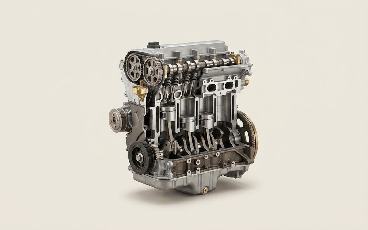 How it works · 3D
How a Car Engine Works
How the part you're working on actually works — in plain English, on a 3D model.
Open in 3D →