Autopapyrus · Ford Kuga II 1.6 EcoBoost JQMA (2013)
https://autopapyrus.com/catalog/ford/kuga/guides/crankcase-ventilation-hose-replacement/
https://autopapyrus.com/catalog/ford/kuga/guides/crankcase-ventilation-hose-replacement/
Compiled automatically from service literature and owner experience. Specs are for the typical configuration — check them against your exact car before you start.
Ford Kuga II 1.6 EcoBoost JQMA (2013): Replacing the Crankcase Ventilation Hoses
The crankcase ventilation system on the 1.6 EcoBoost (JQMA) consists of hoses running from the valve cover and oil separator to the intake tract, before and after the turbocharger. Over time the rubber cracks. The resulting unmetered air leak raises idle speed, makes the tachometer needle "hang," causes a whistling sound from the intake, and leads to oil seepage and a fuel smell. This guide covers the most common case: replacing the main ventilation hose and related connecting pipes with access from the top.
Parts
4| № | Part | Alternatives |
|---|---|---|
| 01 | Crankcase ventilation hose, 1.6 EcoBoost, quick-connect fittingsFind on Amazon → | AlternativesGatesRostecoFord |
| 02 | Intake manifold seal kit (intake manifold gasket/O-rings, crankcase ventilation valve seal)when disassembling the intakeFind on Amazon → | |
| 03 | Hose clampswhen disassembling the intakeFind on Amazon → | |
| 04 | Hose retaining clipsnewFind on Amazon → |
Amazon links search by the part name; use Amazon's fit check for your car before ordering. We may earn a commission from qualifying purchases.
Tools
7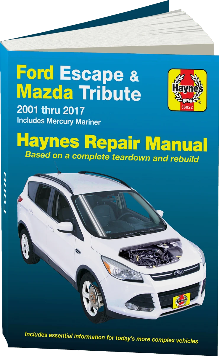 There's a full repair manual for this car
Every system, wiring diagrams and torque specs — not just this job. Haynes and 7 more.
See manuals →
Step by step
26 steps · 6 stagesStage 1 of 6 Diagnosis and preparation 5 steps
- Let the engine cool down and park the car on level ground. Open the hood and inspect the ventilation hoses running from the valve cover and oil separator: look for cracks, oil seepage, traces of fuel, and loose fit on the nipples.
- Check the connectors: the hose must sit tightly on the valve cover nipple and on the intake air duct. A disconnected or torn hose is a common cause of fuel smell and high idle speed.
- To diagnose an air leak, start the engine and carefully pinch (do not squeeze hard) the suspect hose: if the idle speed changes and the whistling disappears, the hose is bad.
- Prepare the new pipes and compare them with the ones being replaced: length, shape, quick-connect type, and diameters must match.
- Disconnect the negative battery terminal and wait 5 minutes. Take photos of the hose and connector layout before disassembly.
Stage 2 of 6 Access 4 steps
- Remove the decorative engine cover (if fitted).
- Disconnect the air duct between the air filter and the turbocharger: loosen the clamps and unclip the sensor connector if one is mounted on the duct. Move the duct aside.
- If the hose you need runs under the intake manifold and cannot be reached, prepare for partial intake disassembly: disconnect the sensor connectors and vacuum hoses (photograph and label them). Note that space is tight and the manifold lifts only a small amount, with the brake booster vacuum hose and wiring getting in the way.
- Remove the intake manifold with the throttle body to the extent needed: remove the mounting bolts (small ratchet with extensions), move the manifold aside and secure it so it does not strain the wiring and lines. If you need to remove the brake booster vacuum hose for clearance, remove it and refit it afterward. Cover the open ports with a clean rag so nothing falls into the engine.
Stage 3 of 6 Removing the old hoses 5 steps
- Release the quick-connect fittings: press the retainer and pull the hose along the axis of the nipple. Do not rock the fitting or use sharp tools, as you could break the valve cover nipple.
- If a fitting is stuck, warm it with your hand or warm air and carefully pry the retainer with a flat-blade screwdriver. Do not use a blowtorch.
- Remove the hose from the oil separator and from the valve cover, and pull it out of the clips. If necessary, an old hose with fittings that will not release can be cut off, since it is being replaced anyway.
- Inspect the nipples on the valve cover, the oil separator, and the intake tract: wipe off the oil and check for cracks or damaged seals.
- If you see a lot of oil in the intake, check the oil separator: if there is oil seepage around the separator cover or the gasket is damaged, replace the gasket and the crankcase ventilation valve.
Stage 4 of 6 Installing the new hoses 4 steps
- Compare the new hose with the old one on the bench: shape, length, fittings, and the orientation of the bends.
- Install the new hose: first into the clips, then push the fittings onto the nipples until the retainer clicks. Pull on the hose; it must not come off.
- Make sure the hose does not touch hot parts (exhaust manifold, turbocharger) or moving parts, and is not chafing against brackets.
- If clamps are used on the pipes, install new ones and tighten them moderately, without pinching the hose.
Stage 5 of 6 Reassembly 4 steps
- Refit the intake manifold with new seals. Tighten the bolts in a crisscross pattern with a torque wrench: approximately 8-12 N·m (6-9 lb-ft); confirm the exact value in the manufacturer's service manual.
- Reconnect all sensor connectors and vacuum hoses using your photos, and refit the brake booster vacuum hose.
- Install the air duct to the turbocharger and tighten the clamps moderately, approximately 3-5 N·m (2-4 lb-ft) (per the manufacturer's specification), and make sure the sensor connector is seated firmly.
- Install the decorative cover and reconnect the negative battery terminal.
Stage 6 of 6 Checking 4 steps
- Start the engine and let it idle for 5-10 minutes. The idle speed should stabilize, and the tachometer needle should not "hang" when you lift off the throttle.
- Listen to the intake: there should be no whistling. Check for any fuel smell.
- Clear any remaining fault codes with a scan tool (lean mixture, idle adaptation errors) and let the engine relearn at idle.
- Take a test drive and afterward inspect the hoses and connectors again for seepage and loose fits.
Common mistakes and warnings
- You are working near the fuel rail and intake system: do not smoke or work near open flames, and cover open ports with a clean rag when the manifold is removed, because any foreign object in a cylinder will cause serious engine damage
- The torque values above are approximate; verify the exact values in the manufacturer's service manual
- If you have no experience working on the intake, leave removal of the manifold to a repair shop
Spotted a mistake? Tell us →
Our articles
 Brand stories
The History of Ford
Ford Motor Company is the largest American automaker by heritage and one of the most recognizable car brands in the…
Read →
 Garage
Fuel Quality Indicators: What Octane and Cetane Numbers Mean
What is an octane number? What about a cetane number? Which fuel should you choose for a high-compression engine?…
Read →
 Before you buy
How to Pick Up Your Car from the Dealership the Right Way
If you've decided to buy a car from a dealership, it isn't enough to simply choose a model you like, pay for it, and…
Read →