https://autopapyrus.com/catalog/toyota/corolla/guides/valve-replacement-and-valve-seat-lapping-on-the-cylinder-head/
Toyota Corolla 1.6 VVT-i 1ZR-FE (2013): Valve Replacement and Valve Seat Lapping on the Cylinder Head
The 1ZR-FE engine is a 16-valve DOHC with a timing chain drive, so there is no timing belt. To replace the valves and lap the seats, you need to remove the cylinder head, disassemble the valve train, and measure the parts. Lapping without measuring is pointless: a worn seat or guide cannot be fixed by lapping and must be machined. Take exact wear limits and torque specifications from the factory service manual for the 1ZR-FE, because there are no reliably confirmed figures for this engine in open sources.
Diagram: where valves, springs, bolts and timing chain are on the head
- 1Valve spring: sits on the valve under the retainer. Compress it with a valve spring compressor to remove the valve.
- 2Spark plug well: remove coils and plugs before disassembly, then clean and wash the head.
- 3Head bolt: loosen from the edges to the center in several passes, fit new ones per the service manual pattern.
- 4Timing chain with sprockets and VVT-i phaser: align the marks before removal and secure the chain with wire.
- 5Chain tensioner: removed with the timing drive, recheck the marks on assembly.
- 6Collets and retainer: hold the spring. Collets release after a light tap on the compressor, on assembly they must seat in the grooves.
- 7Valve stem seal (oil seal): always fit a new one with the special drift.
Parts
9| № | Part | Genuine part no. | Alternatives |
|---|---|---|---|
| 01 | Intake and exhaust valves for 1ZR-FE16 pcs (full set), if worn or burntFind on Amazon → | 13711-37020 | |
| 13711-0T040 | |||
| 02 | Valve stem oil sealssetFind on Amazon → | ||
| 03 | Engine gasket set for cylinder head (head gasket, valve cover gasket, manifold seals)Find on Amazon → | 04111-0T084 | AlternativesVictor ReinzElring |
| 04111-0T083 | |||
| 04 | Cylinder head boltssingle-use, replace with newFind on Amazon → | 11101-39686 | |
| 11101-09300 | |||
| 05 | Engine oilFind on Amazon → | ||
| 06 | Oil filterFind on Amazon → | ||
| 07 | CoolantFind on Amazon → | ||
| 08 | Valve guidesif neededFind on Amazon → | ||
| 09 | Valve springsif neededFind on Amazon → | 90501-31027 |
Amazon links search by the part name and genuine number; use Amazon's fit check for your car before ordering. We may earn a commission from qualifying purchases.
Part numbers are from the manufacturer's original catalogue. Check them against your VIN before ordering.
Tools
14- Socket and wrench set Amazon →
- torque wrench Amazon →
- valve spring compressor for overhead-cam engines Amazon →
- magnet or tweezers for valve keepers Amazon →
- valve stem seal remover and installation tool (seal driver) for new seals Amazon →
- lapping compound (coarse and fine) with a suction-cup lapping stick or a drill at low RPM Amazon →
- micrometer Amazon →
- bore gauge Amazon →
- caliper Amazon →
- feeler gauges Amazon →
- straightedge Amazon →
- marker Amazon →
- timing chain locking tools Amazon →
- drain pans for oil and coolant Amazon →
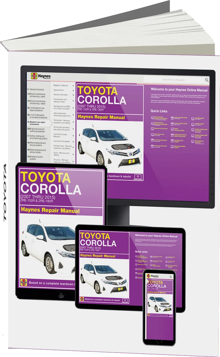 There's a full repair manual for this car
Every system, wiring diagrams and torque specs — not just this job. Haynes and 18 more.
See manuals →
Step by step
21 steps- Confirm the diagnosis before disassembly: measure compression in each cylinder or perform a leakdown test. Low compression in one or two cylinders that does not rise after adding oil points to a burnt or leaking valve. This distinguishes a valve problem from piston ring wear.
- Disconnect the negative battery terminal. Drain the coolant and engine oil. Remove the air filter with its ducts, the cooling system hoses, the fuel rail with injectors (relieve the fuel system pressure beforehand), the ignition coils and spark plugs, the sensor connectors, and the wiring harnesses.
- Remove the intake manifold with the throttle body and the exhaust manifold together with the catalytic converter. Treat the exhaust bolts and studs with penetrating oil before loosening them, as they often seize. Replace the old gaskets.
- Remove the valve cover. Turn the crankshaft and set the No. 1 cylinder piston to top dead center on the compression stroke. Align the marks on the camshaft sprockets and on the chain, and if necessary make your own marks with a marker. This is critical for a VVT-i engine: if the chain is off by one tooth, the cam timing will be wrong.
- Remove the timing drive from the front cover: the VVT-i phaser and camshaft sprockets, and the chain tensioner. Secure the chain with wire or a locking tool so it does not fall into the cover. Do not turn the crankshaft with the sprockets removed.
- Loosen the cylinder head bolts in sequence from the outside to the center, in several passes. Check the 1ZR-FE service manual for the sequence and the number of passes. Remove the cylinder head, prying it gently at the points designed for this if needed. Do not hit the head or insert a screwdriver between the mating surfaces. Cover the cylinder openings with clean rags.
- Remove the camshafts: loosen the bearing caps gradually in the reverse order of tightening, and lay the caps out in order. Remove the lifters and adjusting shims (if fitted to the engine), and lay them out by cylinder and valve number so you can return them to their original positions.
- Remove the valves: place the spring compressor on the spring retainer, give the compressor head a light tap so the keepers come loose, then remove the keepers, retainer, and spring. Pull out the valve and immediately lay it out in order on a stand (poke holes in a piece of cardboard and label the numbers). Remove the valve stem seals with pliers or a seal remover. Always install new seals.
- Clean the cylinder head of carbon and oil, and flush the combustion chambers and ports. Do not scratch the surface that mates with the block with abrasives. Inspect the head for cracks, especially between the seats.
- Measurements: check the head flatness with a straightedge and feeler gauge, measure the valve stem with a micrometer and the guide bore with a bore gauge to determine the stem-to-guide clearance. Check the valve margin (the cylindrical edge on the valve head), runout, and wear on the stem tip, as well as spring length and squareness. Wear limits for the 1ZR-FE are per the manufacturer's specification. Replace valves with a bent stem, burning, a thin margin, or guide wear. If the guide or flatness limits are exceeded, work with a machine shop (pressing in guides, cutting the seats, resurfacing the head).
- If the seats have minor pitting or deposits but the dimensions are within limits, perform lapping. Apply a thin layer of coarse compound to the face of a new or serviceable valve, insert the valve into the guide, and turn it with the suction cup using back-and-forth rotating motions while lifting the valve slightly. The compound must not get into the gap between the stem and the guide. Finish with fine compound. A good result is an even matte ring without gaps around the full circumference of both the seat and the valve.
- Thoroughly wash the cylinder head, valves, and guides to remove all compound residue, dry them, and blow out the ports with compressed air. Abrasive residue left in the engine will destroy the cylinders in a short time.
- Check sealing: temporarily install the valves with springs but without seals, or pour kerosene or solvent into the combustion chamber and check for seepage into the ports. Alternatively, check with a pencil or marker: draw lines across the valve face, rotate it in the seat, and make sure the lines are wiped away around the full circle.
- Assemble the valve train: lubricate the stems with engine oil, install the valves in their original positions, fit the new valve stem seals with the special installation tool, then the springs, retainers, and keepers. Tap the end of the stem with a hammer through a soft drift so the keepers seat. Make sure the keepers are seated in the grooves.
- Install the lifters and shims, then the camshafts with their caps on a clean surface, lubricating the journals with engine oil. Tighten the bearing caps gradually, in the sequence and to the torque given in the 1ZR-FE service manual (the torque for an engine of this class is relatively low, so do not use tens of N·m without checking the manual).
- Clean the mating surfaces of the block and head, and make sure the bolt holes contain no oil or coolant. Install a new head gasket with the marking facing up, exactly on the dowels. Lower the head, lubricate the threads and the underside of the head of the new bolts with engine oil (if the service manual calls for it), and tighten with a torque wrench in several passes in order from the center outward, with an angle-tightening step if one is specified. Torque and angles are strictly per the manufacturer's specification.
- Install the camshafts with the marks aligned, then the chain, sprockets and phaser, and the chain tensioner. Check the marks, turn the crankshaft two full revolutions by hand, and check the marks again. Only after that install the remaining parts.
- Check and, if necessary, adjust the valve clearances per the service manual. Install a new valve cover with its gasket, and tighten the bolts in a crisscross pattern to the low torque given in the manual.
- Install the manifolds with new gaskets, the fuel rail and injectors (new O-rings lubricated with oil), the coils, new spark plugs, the ducts, and the connectors. Tighten the exhaust and intake fasteners per the service manual.
- Fill with fresh oil, install a new oil filter, fill with coolant, and bleed the air from the cooling system. Turn the ignition on for a few seconds so fuel fills the rail, then start the engine and check oil pressure, leaks, and idle smoothness.
- Warm the engine up until the fan comes on, check the coolant level, and top it off. After 50-100 km, check the oil and coolant levels and inspect the cylinder head and manifolds for leaks. Do not put the engine under heavy load for the first 500-1000 km.
Common mistakes and warnings
- Timing marks and chain position are the most common source of mistakes: if the cam timing is off, the valves will hit the pistons, and the work will have to be repeated
- Cylinder head bolts are generally single-use and must be tightened strictly in the sequence and to the torque in the service manual, so do not repeat the old tightening
- Lapping is not a substitute for replacing worn guides and seats: if the stem-to-guide clearance is large or the seat face is uneven, take the head to a machine shop for seat cutting
- Torque values are not given in this guide because there are no confirmed values for the 1ZR-FE, so check the exact values in the manufacturer's service manual
Spotted a mistake? Tell us →
Our articles
 Before you buy
What Car to Buy for 1.5 Million Roubles: New, Used and Five Questions Before You Pay
A new Haval Jolion costs from 2,099,000 roubles, not 1.45 million. We compared new car prices with the budget, looked…
Read →
 Brand stories
The History of Toyota
From weaving looms to reliable mass-produced cars.
Read →
 Garage
Fuel Quality Indicators: What Octane and Cetane Numbers Mean
What is an octane number? What about a cetane number? Which fuel should you choose for a high-compression engine?…
Read →