Autopapyrus · Nissan Murano 3.5 V6 VQ35DE (2007)
https://autopapyrus.com/guides/nissan/murano/engine-overhaul/
https://autopapyrus.com/guides/nissan/murano/engine-overhaul/
Compiled automatically from service literature and owner experience. Specs are for the typical configuration — check them against your exact car before you start.
Nissan Murano 3.5 V6 VQ35DE (2007): Engine Overhaul
A VQ35DE overhaul involves removing the engine, fully disassembling it, inspecting and measuring the block and crankshaft, boring and honing the cylinders to an oversize, and replacing the pistons, bearings and valve stem seals. The block is aluminum with cast-iron liners. Boring, honing and crankshaft journal grinding can only be done by a machine shop with the proper equipment. Plan in advance to replace the timing chains, tensioners and guides: they are located on the transmission side, and it is inconvenient to take the engine apart again just to get to them.
Parts
15| № | Part |
|---|---|
| 01 | Piston and ring set for VQ35DE (oversize or standard) |
| 02 | Main and rod bearings |
| 03 | Engine gasket set (cylinder heads, oil pan, valve covers) |
| 04 | Cylinder head bolts (single-use, torque-to-yield) |
| 05 | Connecting rod bolts (single-use, torque-to-yield) |
| 06 | Main bearing bolts (single-use, torque-to-yield) |
| 07 | Valve stem seals |
| 08 | Timing chain set (chains, guides, slack guides, tensioners) |
| 09 | Oil pumpif worn |
| 10 | Water pump |
| 11 | Thermostat |
| 12 | Crankshaft seals |
| 13 | Oil filter |
| 14 | Engine oil 5W-30 (API SL/SM or newer) |
| 15 | Coolant |
Tools
15- lift or pit
- engine hoist (shop crane)
- engine stand
- socket and wrench set
- torque wrench (including a low-range one)
- angle gauge for torque-plus-angle tightening
- pullers
- bore gauge and micrometers
- feeler gauges
- Plastigage
- piston ring compressor
- valve stem seal installation tool
- flywheel (driveplate) holding tool
- labeled assembly kit
- gasket sealant for mating surfaces
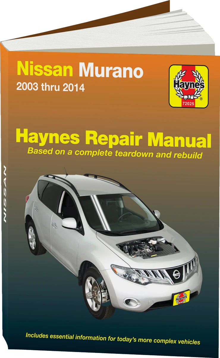 There's a full repair manual for this car
Every system, wiring diagrams and torque specs — not just this job. Haynes and 4 more.
See manuals →
Step by step
19 steps- Preparation. If possible, measure compression and oil pressure to record the baseline condition. Disconnect the negative battery terminal and relieve fuel system pressure (remove the fuel pump fuse or relay and run the engine until the fuel is used up). Drain the oil and coolant (the oil pan drain plug is tightened to about 30-40 N·m (22-30 lb-ft)). Photograph the wiring harnesses, hoses and connectors.
- Removing accessories and engine bay components. Remove the skid plate, the air intake with the mass airflow (MAF) sensor, the throttle body, the radiator with fans (as needed), the drive belts, the alternator, the A/C compressor (set it aside without opening the refrigerant circuit), and the power steering pump. Disconnect the fuel lines, the cooling system and heater hoses, the exhaust pipes with catalytic converters, and the wiring harnesses.
- Removing the engine. On the Z50 the engine is mounted transversely and is connected to the transmission, so removal is done in one of two ways: the engine alone, or together with the transmission and subframe. Choose the option your equipment allows. Disconnect the driveshafts beforehand (if removing as an assembly), hang the engine from the hoist using the factory lifting brackets, remove the mounts and carefully lift the unit out. If the engine is removed on its own, separate it from the CVT, supporting the CVT.
- Mounting on the stand and disassembly. Secure the block on the stand. Remove the intake manifold, the fuel rail with injectors, the ignition coils and spark plugs, the valve covers, the drive belts, the crankshaft pulley, the front and rear covers, the oil pans (upper and lower), the oil pickup tube, the oil pump, the water pump and the thermostat. Label everything that must go back in its original position: lifters, timing components, connecting rod caps.
- Timing system. Before removing the chains, set the No. 1 piston to TDC and photograph the marks on the chains and sprockets. Remove the tensioners, guides, chains, camshaft sprockets and gears (the chain drive is located on the transmission side). Install new parts according to the marks (colored chain links to the gear marks). If in doubt, install the chain according to the engine's service manual.
- Removing the cylinder heads. Loosen the cylinder head bolts in the reverse of the tightening sequence and in several passes so the heads do not warp. Remove both heads and clean the block surfaces of any gasket residue without scratching the aluminum.
- Inspecting and repairing the cylinder heads. Check the surface for warpage (with a straightedge and feeler gauge), inspect the seats and guides, and measure the clearances. Replace the valve stem seals: remove the valve keepers to take out the valves, then install a new seal on each with the installation tool. If the guides or seats are worn, take the heads to a machine shop. Lap the valves or replace them as needed.
- Removing the piston assemblies. Remove the lower part of the block (oil pan, and the ladder/main bearing frame if equipped), remove the connecting rod caps and pull out the pistons with the rods. Label the pistons by cylinder, and do not mix up the caps and rods. Note any carbon buildup and the wear "ridge" at the top of the cylinder.
- Removing the crankshaft. Remove the main bearing caps, marking their order and orientation, lift out the crankshaft, and remove the bearings (without mixing them up between their seats). Inspect the journals for scoring, out-of-roundness and taper. Check the crankshaft runout and the oil passages.
- Inspecting and boring the block. Wash the block thoroughly and blow out the oil passages. Measure the cylinders with a bore gauge (out-of-roundness, taper) at several levels and in several planes. If wear or scoring is out of tolerance, the machine shop bores and hones the block to the oversize piston dimension (the size must match the piston set exactly, and honing should be done with a torque plate installed or with simulated load where possible). Measure the pistons and determine the piston-to-cylinder clearance according to the engine's service manual. If necessary, grind the crankshaft journals to the undersize of the bearings.
- Selecting bearings. Main and rod bearings are selected based on the measurements of the journals and bearing seats. Check the oil clearances with Plastigage and compare the values to the manufacturer's tolerances. Do not file or modify the bearings to fit.
- Assembling the lower end. Wash the block and passages thoroughly, and lubricate the bearings and journals with assembly oil. Lay in the crankshaft and tighten the main caps in the order specified by the manufacturer: in stages, with an angle turn at the end. Use new torque-to-yield bolts. Check that the crankshaft turns freely and check the end play.
- Pistons and rings. Check the ring end gaps in the cylinder and the ring groove clearances. Install the rings according to the TOP marks and stagger the gaps according to the service manual (offset the gaps relative to each other). Install the pistons with a ring compressor, with the mark on the piston crown facing the front of the engine (per the service manual). Tighten the connecting rod caps with new bolts in stages with an angle turn, and rotate the crankshaft after each rod.
- Oil pump and pans. Install the oil pump (with a new seal and gaskets), the oil pickup tube, and the pans with sealant according to the proper procedure: apply an even bead, wait for the sealant set time, and tighten the pan fasteners lightly with a torque wrench to the service manual specification.
- Cylinder heads and timing. Install new gaskets and the heads, and tighten the new cylinder head bolts strictly according to the pattern and in several stages with an angle turn (values and sequence are in the VQ35DE service manual). Install the camshafts, chains, tensioners and guides according to the marks, and check that the marks line up after turning the crankshaft by hand two or three revolutions. Install the valve covers with new gaskets, applying sealant at the joints according to the proper procedure, and use the low torque values specified in the service manual.
- Accessories and peripherals. Install the new water pump and thermostat, the crankshaft seals, the intake manifold, the fuel rail, the injectors with new seals, and the coils and spark plugs (the spark plugs are tightened to about 20-25 N·m (15-18 lb-ft)). Replace the belts and pulleys, and install the alternator, A/C compressor and power steering pump.
- Installing the engine. Install the engine in the reverse order, connect it to the CVT, and tighten the mounts and fasteners to the manufacturer's specifications. Connect all hoses, harnesses, fuel and coolant lines, and the exhaust system with new gaskets.
- First start. Fill with new 5W-30 oil and a new filter (capacity about 4.5-5 L (4.8-5.3 qt), check with the dipstick), fill with coolant, and bleed the air from the system. Before starting, crank the engine with the starter without fuel (fuel pump fuse removed) until oil pressure appears. Then start the engine, warm it up at moderate rpm with no load, and check for leaks and trouble codes.
- Break-in. For the first 1,000-1,500 km, avoid hard loads and high rpm, and do not hold a constant engine speed. After 500-1,000 km, replace the oil and filter, then check the coolant level and the tightness of accessible connections.
Common mistakes and warnings
- The VQ35DE cylinder head bolts, connecting rod bolts and main bearing bolts are single-use, torque-to-yield
- Reusing them leads to loss of clamping force and failure of the joint
- Do not tighten them by feel: you need a torque wrench and an angle gauge, and the values and sequence must come from the manufacturer's service manual
- Working on the fuel system and lifting the engine are dangerous: use a serviceable hoist, support components with safety stands, and keep open flame away
- If you have no experience with engine overhauls and no access to a machine for boring and honing, leave the assembly to a professional engine shop
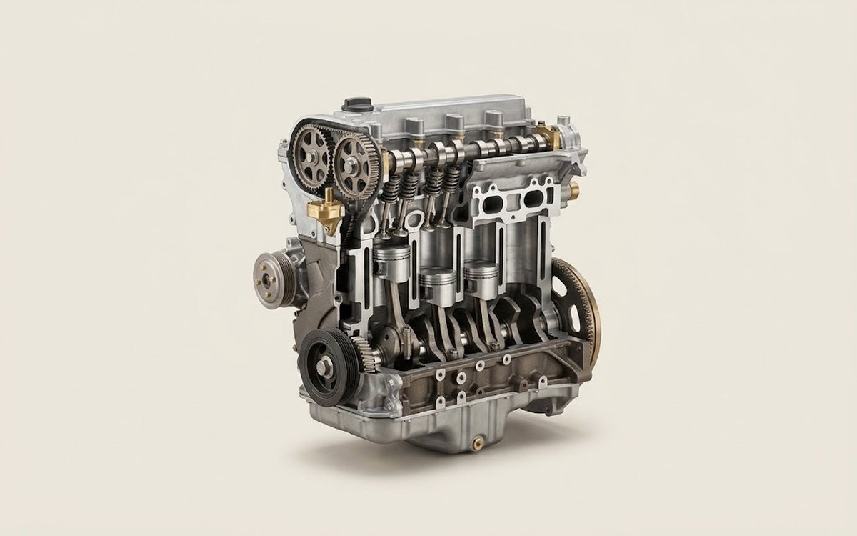 How it works · 3D
How a Car Engine Works
How the part you're working on actually works — in plain English, on a 3D model.
Open in 3D →