Autopapyrus · Nissan Pathfinder R50 3.3 V6 VG33E (1997)
https://autopapyrus.com/guides/nissan/pathfinder/clutch-disc-pressure-plate-and-release-bearing-replacement/
https://autopapyrus.com/guides/nissan/pathfinder/clutch-disc-pressure-plate-and-release-bearing-replacement/
Compiled automatically from service literature and owner experience. Specs are for the typical configuration — check them against your exact car before you start.
Nissan Pathfinder R50 3.3 V6 VG33E (1997): Clutch Disc, Pressure Plate and Release Bearing Replacement
Replacing the clutch on a Pathfinder R50 with the VG33E requires removing the transmission completely. The job is labor-intensive and requires a lift, or a pit with a jack to support the transmission. The critical point is removing the crankshaft position sensor before pulling the transmission. Otherwise, the transmission housing will destroy it.
Part
- 🔩 Clutch kit for VG33E (250 mm 24-spline disc, pressure plate, release bearing, pilot bushing, alignment tool). Popular manufacturers: Aisin, Exedy, LuK, Valeo
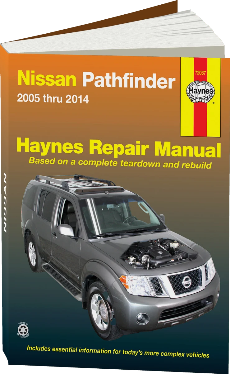 There's a full repair manual for this car
Every system, wiring diagrams and torque specs — not just this job. Haynes and 15 more.
See manuals →
Step by step
26 steps- Disconnect the negative battery terminal. Raise the vehicle with a jack and set it on jack stands on a level surface.
- Drain the oil from the transfer case (drain plug on the bottom of the case). Disconnect both driveshafts (front and rear): remove the flange bolts and mark their positions for reassembly.
- Remove the interior parts: ashtray, center console, shift lever and transfer case lever boots, and lever knobs.
- You MUST remove the 10 mm bolt of the crankshaft position sensor (Nissan 23731-EC00A). It is located at the engine-transmission joint, on top at the right. If you don't remove it, the sensor will be destroyed when the transmission is separated from the block.
- Disconnect all electrical connectors from the transmission and transfer case (reverse light switch, 4WD connector, speed sensor). Remove the shift cables and linkage.
- Support the transmission from below with a jack (place a wooden block under the transmission pan to protect it). Remove the transmission crossmember (4 bolts to the frame).
- Remove the bolts that hold the transmission to the engine. Start with the lower ones (accessible from below), then the upper ones (use 14 mm swivel sockets on 600 mm long extensions, working through the wheel arches or from above).
- Slowly lower the transmission on the jack, moving it rearward to separate it from the engine block. Check that all connections are disconnected. Remove the transmission from under the vehicle.
- Inspect the flywheel for cracks, scoring and overheating (blue discoloration). If the surface is rough, it can be resurfaced with medium-grit sandpaper. If there is deep damage or warping, replace the flywheel.
- Remove the 6 bolts that hold the pressure plate to the flywheel. Loosen them evenly in a crisscross pattern so the pressure plate does not distort. Remove the pressure plate together with the disc.
- Check the disc lining wear. The minimum thickness above the rivets is 0.8 mm. If it is thinner than that, or if the disc is oil-soaked, replacement is mandatory.
- Remove the old pilot bushing from the center of the crankshaft using a puller or a drift of the appropriate diameter. Press in the new bushing from the kit with light taps through a drift.
- Clean the flywheel surface and the pressure plate contact surface with solvent and wipe them dry. Do not let any oil or grease get on the friction surfaces.
- Install the new clutch disc on the flywheel with the protruding hub facing the TRANSMISSION (the "flywheel side" marking or arrow must face the flywheel). Insert the alignment tool through the disc into the pilot bushing.
- Place the new pressure plate on the flywheel and align the holes. Start all 6 bolts by hand.
- Tighten the pressure plate bolts in a crisscross pattern in several passes (first snug, then 50%, then 100%) to 83-113 N·m (61-83 lb-ft). Use a torque wrench. Remove the alignment tool.
- On the transmission input shaft, remove the old release bearing: compress the spring clips and slide it back off the guide sleeve. Install the new bearing until the clips click into place.
- Apply a thin layer of high-temperature grease (molybdenum or graphite) to the input shaft splines. Do not overdo it, because the excess will get onto the disc.
- Raise the transmission on the jack and align it with the engine block. Make sure the input shaft enters the disc splines and the pilot bushing without binding. Do not use force. If it does not go in, lower the transmission and repeat the alignment.
- Install the upper bolts that hold the transmission to the engine (14 mm), then the lower ones. Tighten all bolts in a crisscross pattern with a torque wrench to 40-50 N·m (30-37 lb-ft).
- Install the crossmember and tighten the frame bolts to 50-60 N·m (37-44 lb-ft). Remove the jack from under the transmission.
- You MUST reinstall the crankshaft position sensor. Tighten the 10 mm bolt to 8-10 N·m (71-89 lb-in).
- Reconnect the driveshafts (align the marks you made), the electrical connectors, the cables and the shift linkage.
- Fill the transfer case with oil to the level of the check hole (about 1.2 L (1.3 qt) of API GL-4 or GL-5 75W-90).
- Reinstall the interior parts (lever knobs, boots, console, ashtray). Connect the battery.
- Start the engine and check gear shifting while stationary. Take a test drive. The clutch should engage smoothly, without jerking, slipping or unusual noises.
Common mistakes and warnings
- The pressure plate bolt torque is critical. Under-tightening will cause vibration and destroy the pressure plate, and over-tightening will cause distortion and uneven disc wear. Always use a torque wrench. Don't forget to remove the crankshaft position sensor before removing the transmission, because replacing it will cost more than the whole job. If you have no experience with manual transmissions and heavy components, it is recommended to go to a specialized repair shop.
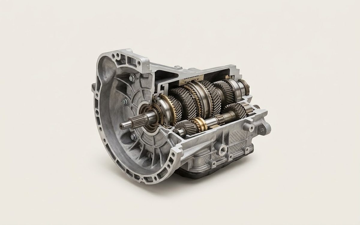 How it works · 3D
How a Manual Transmission Works
How the part you're working on actually works — in plain English, on a 3D model.
Open in 3D →