Autopapyrus · Nissan Atlas-Condor (1st generation)
https://autopapyrus.com/guides/nissan/atlas-condor/upper-front-control-arm-replacement/
https://autopapyrus.com/guides/nissan/atlas-condor/upper-front-control-arm-replacement/
Compiled automatically from service literature and owner experience. Specs are for the typical configuration — check them against your exact car before you start.
Nissan Atlas-Condor (1st generation): Upper Front Control Arm Replacement
This generation of Atlas/Condor has an independent front suspension with double wishbone (upper and lower control arms). The upper arm pivots on a shaft with bushings mounted to the frame, and connects to the steering knuckle through a ball joint. Most often it is the worn bushings or the ball joint that get replaced. If the arm is bent or the threads and mounting surfaces are worn out, replace the whole arm. A wheel alignment is required after the replacement.
Part
- 🔩 front upper control arm (left and right, complete with ball joint or separate), upper control arm bushings, upper control arm ball joint, arm shaft mounting hardware kit (bolts/nuts/cotter pins). Exact part numbers depend on the production date, load rating version and wheelbase, so go by the part name and match it to your old arm
Step by step
15 steps- Park the vehicle on level ground, set the parking brake and chock the rear wheels. Loosen the wheel nuts on the side you are working on, then lift the front end with the jack and place jack stands under the frame. Remove the wheel.
- Generously apply penetrating oil to both arm-to-frame mounts, the ball joint nut and the bolts, and let it soak for 10-15 minutes. Clean the threads with a wire brush.
- Assess the condition: rock the wheel up and down, check the ball joint play with a pry bar, inspect the bushings for cracks and rubber squeezing out, and check the arm for deformation. This will help you decide whether to replace only the bushings or the whole arm.
- If the suspension is loaded by a torsion bar or a spring, keep in mind that the load can be released suddenly when the arm is disconnected. Support the lower arm or the knuckle with a jack and do not let the assembly drop freely. Determine the correct way to relieve the load on your version by understanding how the arm is loaded, rather than blindly undoing fasteners.
- If they are in the way, disconnect any sensors and hoses from the upper arm or knuckle, and remove the bump stop/travel limiter if it is mounted on the arm. Do not stretch the brake hose or let the caliper hang from it: support the caliper with a piece of wire.
- Remove the upper ball joint nut (pull the cotter pin first) and press the stud out of the knuckle with a separator. Avoid striking the stud and knuckle with a hammer without support, so you do not damage the threads or the tapered seat.
- Before undoing the arm shaft mounting to the frame, make position marks (with a marker on the washers or shims). If the shaft has eccentric washers or alignment shims, note their position and quantity. This will help you restore close to the original alignment angles.
- Remove the bolts/nuts of the arm shaft and take off the arm. If the shaft is seized, apply heat and penetrating oil, and do not shear off the threads.
- If you are replacing only the bushings, press out the old ones with a press or puller and press in the new ones, without letting them go in crooked. For difficult bushings without a press, it is better to replace the complete arm.
- Compare the new arm with the old one (length, shape, position of the mounting points, ball joint design). Clean the mounting surfaces on the frame and the knuckle.
- Install the arm in place and tighten the arm shaft bolts by hand only, without final tightening.
- Insert the ball joint stud into the knuckle, tighten the nut and secure it with a new cotter pin. Take the torque specification from the manufacturer's manual for your model year, as it depends on the thread size. Do not guess the numbers.
- Final-tighten the arm shaft fasteners ONLY when the suspension is at its normal working position (vehicle lowered onto its wheels), otherwise the rubber bushings will be preloaded in a twisted position and will fail quickly.
- Install the wheel and tighten the nuts in a crisscross pattern, lower the vehicle, and retighten the wheel nuts with a torque wrench to the specified torque. Check all cotter pins, hoses and connectors.
- Take a test drive at low speed: check for knocks, steering wheel vibration and pulling. Then have the wheel alignment (camber/toe) done on an alignment rack.
Common mistakes and warnings
- The suspension and steering are safety-critical systems. If you lack the experience and the proper equipment to safely lift the truck and relieve the suspension load, leave the job to a repair shop. Do not rely on a jack alone without safety stands. A wheel alignment check and adjustment is required after the replacement, otherwise you will get rapid tire wear and unstable handling on the road. Check the exact torque specifications and the procedure for relieving suspension load for your version against the manufacturer's manual.
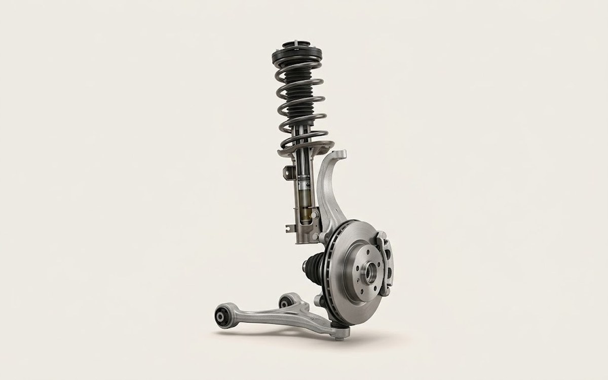 How it works · 3D
How Car Suspension Works
How the part you're working on actually works — in plain English, on a 3D model.
Open in 3D →