Autopapyrus · Chevrolet Rezzo (1st generation)
https://autopapyrus.com/guides/chevrolet/rezzo/front-lower-control-arm-assembly-replacement/
https://autopapyrus.com/guides/chevrolet/rezzo/front-lower-control-arm-assembly-replacement/
Compiled automatically from service literature and owner experience. Specs are for the typical configuration — check them against your exact car before you start.
Chevrolet Rezzo (1st generation): Front Lower Control Arm Assembly Replacement
The Rezzo's front lower control arm attaches at two points to the subframe or body and at the ball joint to the steering knuckle. The arm is replaced as an assembly when the ball joint and bushings are worn: knocking over bumps, play, pulling to one side, and uneven tire wear. Replacing the complete assembly saves you from pressing bushings in, which requires a press. Exact torque specifications for this model were not found in publicly available service materials, so the values below are approximate guidelines.
Part
- 🔩 Front lower control arm, left and right, complete with ball joint and bushings (for the Rezzo 1.6, equivalents from Febi Bilstein, Febest and other manufacturers are listed in catalogs). The left and right arms are different. Compare the shape and mounting points with the old part
 There's a full repair manual for this car
Every system, wiring diagrams and torque specs — not just this job. Haynes AutoFix (online).
See manuals →
Step by step
11 steps- Park the car on level ground, set the parking brake, and chock the rear wheels. Loosen the lug nuts on the front side you are working on.
- Raise the front of the car, support it on jack stands, and remove the wheel. If the car has an engine undercover, remove it if it blocks access.
- Apply penetrating oil to the threaded connections of the arm and let it soak for a few minutes. Clean the threads with a wire brush.
- Disconnect the sway bar link from the arm if it is attached to it. Hold the link stud with a wrench to keep it from turning.
- Remove the bolt or nut that secures the ball joint to the steering knuckle. If the ball joint is stuck tight, push it out with a pry bar or a separator. Do not strike the boot or the threads of the ball joint.
- Mark the position of the eccentric (cam) bolts, if there are any (camber/toe adjustment). Remove the bolts that secure the arm to the subframe or body, then remove the arm. The bolts often seize, so use a long breaker bar.
- Compare the new arm with the old one: length, hole positions, direction of the bend, and whether it has a bracket for the sway bar. Check the boots and the tightness of the ball joint.
- Install the new arm and insert the bolts, but only tighten them by hand for now. Connect the ball joint to the knuckle and the sway bar link.
- Do the final tightening of the bushing bolts with the car lowered onto its wheels (or with the arm jacked up under load), so the rubber does not twist while the suspension hangs. The torque for the arm mounting bolts is typically in the range of 80-120 N·m (59-89 lb-ft), and for the ball joint nut approximately 50-80 N·m (37-59 lb-ft), followed by a cotter pin if one is specified. Check the exact values against the manufacturer's specifications.
- Install the wheel, tighten the lug nuts in a star pattern (typically 90-110 N·m (66-81 lb-ft)), and lower the car. Repeat the work on the other side if you are replacing both.
- Be sure to have a wheel alignment done after the replacement. Take a test drive and check that there are no knocks and no pulling.
Common mistakes and warnings
- The suspension is a safety-critical system. Incorrect tightening or a damaged ball joint can lead to loss of control. If you lack experience or the right tools, have a repair shop do the work. Do not tighten the bushings while the suspension is hanging, or they will tear much sooner than they should.
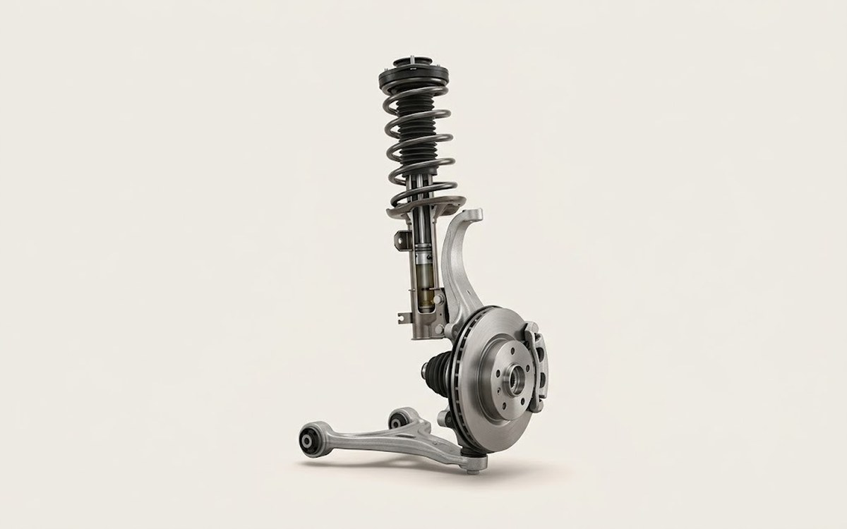 How it works · 3D
How Car Suspension Works
How the part you're working on actually works — in plain English, on a 3D model.
Open in 3D →