Autopapyrus · Audi A6 (C7)
https://autopapyrus.com/guides/audi/a6/front-wheel-bearing-replacement/
https://autopapyrus.com/guides/audi/a6/front-wheel-bearing-replacement/
Compiled automatically from service literature and owner experience. Specs are for the typical configuration — check them against your exact car before you start.
Audi A6 (C7): Front Wheel Bearing Replacement
On the A6 C7, the front bearing comes as a ready-made hub assembly that bolts to the steering knuckle from the inboard side. The knuckle is aluminum, so work carefully: a seized unit must be driven out without striking the mounting surfaces. Replace all fasteners the manufacturer marks as single-use with new ones.
Parts
4| № | Part | Genuine part no. | Alternatives |
|---|---|---|---|
| 01 | Front wheel bearing with hub (complete unit) | 4H0498625C | SKF, FAG/INA, SNR, Febi |
| 8K0407607 | |||
| 02 | Axle center nut (bolt), new | 8E0407643A | |
| 03 | Bearing-to-knuckle boltsif needed | ||
| 04 | Self-locking control arm nutsif needed | WHT006151 | |
| WHT003684 |
Part numbers are from the manufacturer's original catalogue. Check them against your VIN before ordering.
Tools
12- floor jack and jack stands
- lug wrench
- torque wrench
- socket set (including Torx and XZN triple-square bits)
- long breaker bar with extension
- ball joint or control arm puller
- pry bar
- brass drift or hammer
- hub puller (if seized)
- wire brush
- anti-seize compound
- thread locker
 There's a full repair manual for this car
Every system, wiring diagrams and torque specs — not just this job. Haynes AutoFix (online) and 3 more.
See manuals →
Step by step
15 steps- Slightly loosen the lug bolts with the car on the ground. Apply the parking brake and leave the car in Park (or in gear), and chock the opposite wheels.
- Raise the front of the car, set it on jack stands, and remove the wheel.
- Remove the cap/cover from the axle center nut (if fitted). Loosen the axle center nut while the car is still on its wheels or while a second person holds the brakes. The nut is torqued very tightly, so you need a long lever.
- Remove the brake caliper together with its bracket from the knuckle and hang it from a wire or zip tie so the brake hose carries no load. Remove the brake rotor (if needed, remove the rotor retaining screw).
- Disconnect the ABS sensor from the knuckle: pull it out of its bore, and if needed unplug the connector and free the wiring from its clips. If the sensor seat is very dirty, remove the sensor carefully so you don't break it.
- Disconnect the tie rod end from the knuckle, and the sway bar link. Remove the lower or upper control arms as far as needed to swing the knuckle out of the way. The nuts on the control arms are self-locking, so install new ones when reassembling.
- Pull the splined end of the axle shaft out of the hub. If the shaft won't come out, tap it carefully through a protective sleeve, and don't hit the threads. Don't let the axle hang from the inner joint: it must not be bent over sharply, so support the axle with a wire.
- Remove the four bolts that hold the bearing to the knuckle (accessed from the inboard side of the knuckle, usually through holes for the socket heads) and remove the unit. If the unit is seized, heat the seat, apply penetrating oil, and carefully drive it out with a brass drift through the end of the hub.
- Clean the knuckle's mounting surface and centering lip with a wire brush, removing rust and dirt. Apply a thin layer of anti-seize to the centering lip and the axle splines.
- Install the new unit, insert the bolts (new ones if they are single-use), and tighten them in a crisscross pattern. The torque for the bearing-to-knuckle bolts is not clearly confirmed in public sources, so use the value from the manufacturer's specifications for your vehicle. Don't tighten by feel.
- Insert the axle shaft into the hub and tighten the new center nut in two stages per the specification: first to a torque, then with an additional angle turn. Take the exact torque and angle values from the manufacturer's specifications. Don't tighten with an impact wrench.
- Reassemble the control arms, tie rod end and sway bar link, tightening them with the car lowered to the ground rather than hanging on the suspension: fasteners with rubber bushings must be tightened under suspension load.
- Install the ABS sensor, rotor and caliper. Tighten the caliper bracket to specification and clean the threads. Pump the brake pedal firmly until it is hard so the pads seat properly.
- Install the wheel, lower the car, and tighten the lug bolts in a crisscross pattern to 120 N·m (89 lb-ft).
- Check your work: drive 5-10 km on a smooth road, listen for humming and wobble, and check that the ABS light is off on the dash. Then get a wheel alignment: after removing the control arms and tie rod, the alignment will definitely be off.
Common mistakes and warnings
- This job involves the brake system, steering and suspension
- If you lack experience or a torque wrench, take it to a repair shop
- Tightening the lug bolts (120 N·m (89 lb-ft)) and the axle center nut is critical for safety: if they loosen, the assembly will fail
- Always replace the complete unit and never reuse single-use nuts and bolts
- Never work under a car supported only by a jack
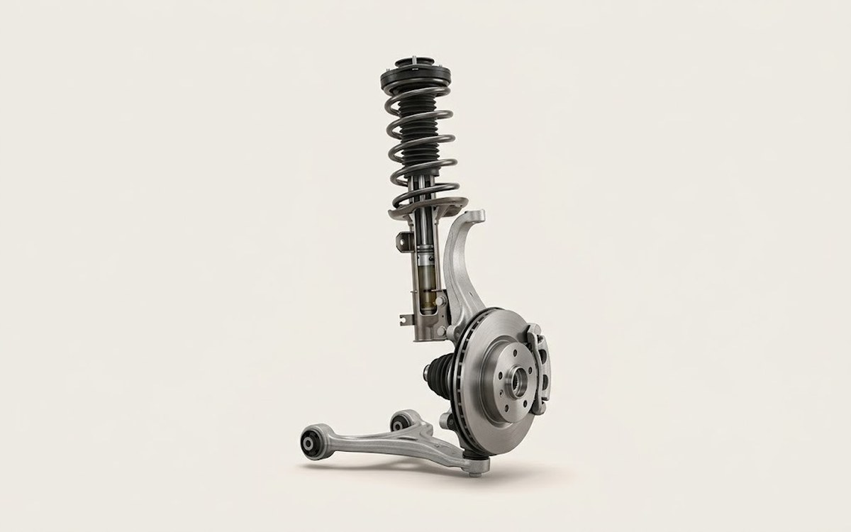 How it works · 3D
How Car Suspension Works
How the part you're working on actually works — in plain English, on a 3D model.
Open in 3D →