Autopapyrus · Lexus ES (XV60)
https://autopapyrus.com/guides/lexus/es/front-lower-control-arm-removal-and-installation/
https://autopapyrus.com/guides/lexus/es/front-lower-control-arm-removal-and-installation/
Compiled automatically from service literature and owner experience. Specs are for the typical configuration — check them against your exact car before you start.
Lexus ES (XV60): Front Lower Control Arm Removal and Installation
The Lexus ES XV60 has a MacPherson strut front suspension. The lower control arm attaches to the subframe at two points (front and rear bushings) and to the steering knuckle through the ball joint. The final tightening of the arm bolts is done with the vehicle on its wheels. Otherwise the bushings become twisted and fail quickly.
Parts
4| № | Part | Alternatives |
|---|---|---|
| 01 | Front lower control arm assembly with ball jointleft or right | Lemförder, TRW, Febest, 555 |
| 02 | Front control arm bushingsif the arm is not replaced as an assembly | |
| 03 | Lower control arm ball jointif the arm is not replaced as an assembly | |
| 04 | Control arm fasteners (self-locking nuts and bolts)replacement recommended |
Tools
9- lift or jack with solid jack stands
- lug wrench
- 14-21 mm sockets and wrenches
- torque wrench
- pry bar or light tire lever
- ball joint separator (if needed)
- penetrating oil
- copper or rubber mallet
- support stand for the hub or brake caliper
 There's a full repair manual for this car
Every system, wiring diagrams and torque specs — not just this job. Haynes and 9 more.
See manuals →
Step by step
14 steps- Park the vehicle on level ground and loosen the lug nuts by 1/2 turn. Shift to P, apply the parking brake, and place wheel chocks behind the rear wheels. On the hybrid, ordinary precautions are enough: you do not need to disable the HV system for this job, and there are no orange cables in the work area. If the vehicle is in READY mode, turn it off and wait until the READY indicator goes out.
- Raise the front of the vehicle, place jack stands for safety, and remove the wheel.
- Remove the lower plastic engine undercover and the fender liner if they block access to the control arm bolts.
- Generously apply penetrating oil to the threads of the control arm bolts and nuts. Mark the position of any eccentric cams or washers with a marker to preserve the camber setting.
- If a stabilizer bar link or a body height sensor (headlight leveling sensor) is attached to the arm, disconnect it. Do not pull on the sensor wiring.
- Remove the nut securing the ball joint to the steering knuckle (or the clamp bolts, depending on the version). While turning the stud, hold it with a hex key or a socket. Press the stud out with a separator or with careful mallet blows on the knuckle eye. Do not strike the stud threads. Do not stretch the dust boot.
- Lower the arm and pull the ball joint out of the knuckle. Do not let the brake hose or the ABS sensor wiring stretch. Hang the caliper on a wire if you had to move it.
- Remove the bolts of the front and rear control arm bushings at the subframe and take off the arm. The bolts may be seized: use an extension bar and, if necessary, heat the area, keeping the flame away from rubber parts and boots.
- Compare the new arm with the old one: length, shape, ball joint and bushing positions, and side (left or right). Inspect the ball joint boot and the mounting surfaces on the subframe and knuckle for corrosion and deformation.
- Position the arm in the subframe, insert the bushing bolts, and snug them by hand without final tightening. Insert the ball joint stud into the knuckle and tighten the nut. The ball joint nut torque is usually in the range of 100-150 N·m (74-111 lb-ft); check the exact value in the manufacturer's specifications. Replace the cotter pin or lock nut if the design includes one.
- Reinstall the parts you removed earlier (stabilizer link, sensor, undercover, fender liner), then the wheel. Tighten the lug nuts by hand in a crisscross pattern.
- Lower the vehicle onto its wheels and bounce the body up and down to settle the suspension. Only now do the final tightening of the control arm bushing bolts with a torque wrench. The torque is usually in the range of 100-180 N·m (74-133 lb-ft); check the exact value in the manufacturer's specifications. Then tighten the lug nuts to 103 N·m (76 lb-ft).
- Check for play, knocking, and boot rubbing during a short test drive at low speed. After 50-100 km, recheck the tightness of the lug nuts and arm fasteners.
- Be sure to have a wheel alignment done after replacing the arm.
Common mistakes and warnings
- The suspension and steering are safety-critical systems
- If you have no experience with spring struts, ball joints, and a torque wrench, leave the job to a repair shop
- Do not tighten the bushing bolts with the suspension hanging, and do not drive the vehicle without an alignment: this leads to rapid tire wear and poor handling
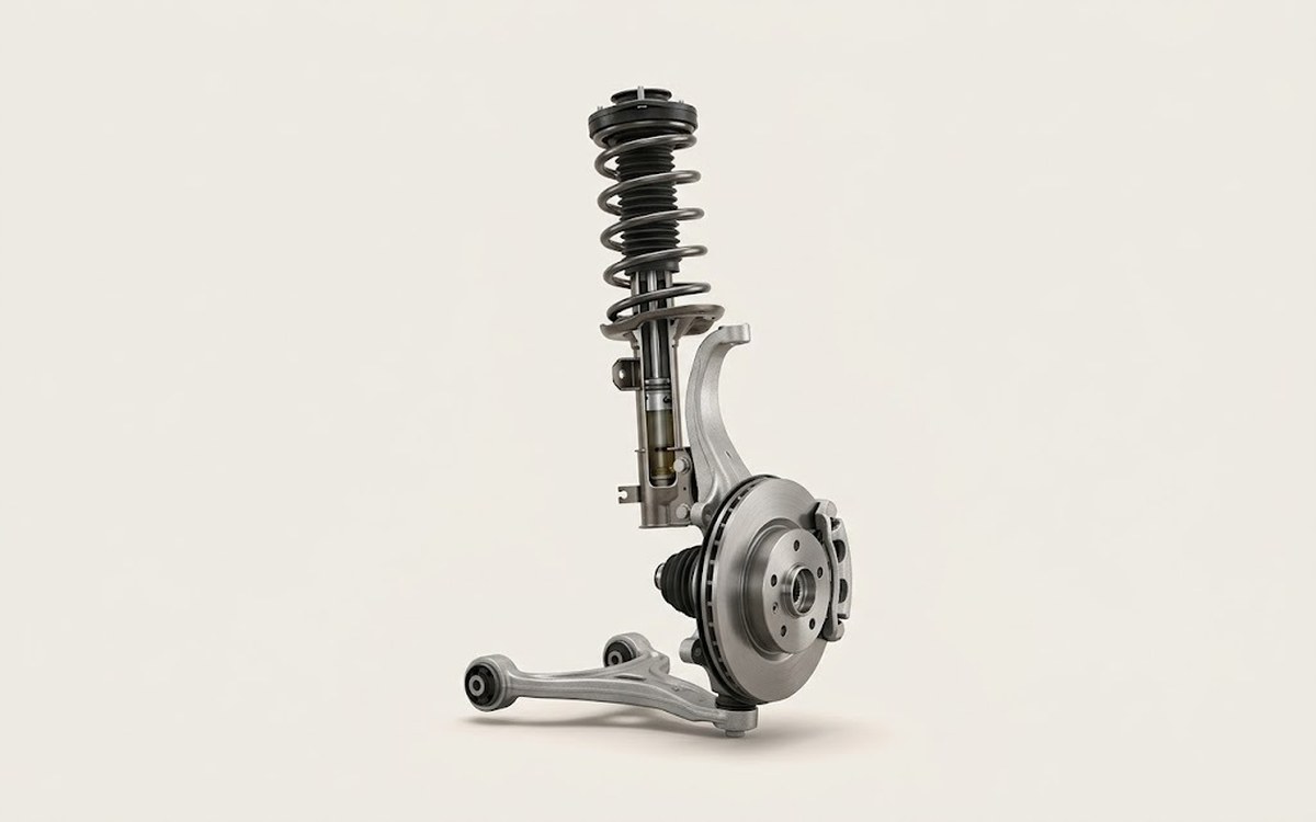 How it works · 3D
How Car Suspension Works
How the part you're working on actually works — in plain English, on a 3D model.
Open in 3D →