Autopapyrus · Mercedes-Benz A-Class W177
https://autopapyrus.com/guides/mercedes-benz/a-class/front-control-arm-bushing-replacement/
https://autopapyrus.com/guides/mercedes-benz/a-class/front-control-arm-bushing-replacement/
Compiled automatically from service literature and owner experience. Specs are for the typical configuration — check them against your exact car before you start.
Mercedes-Benz A-Class W177: Front Control Arm Bushing Replacement
The front lower control arms on the W177 attach to the subframe with two bushings, a front one and a rear one. Wear shows up as clunking over bumps, increased play, and pulling to one side under braking. Replacement requires removing the entire arm and pressing the old bushings out with a press.
Part
- 🔩 Front lower control arm bushings (front and rear on each arm). Manufacturers: Lemforder, Meyle, Febi Bilstein
 There's a full repair manual for this car
Every system, wiring diagrams and torque specs — not just this job. Haynes and 7 more.
See manuals →
Step by step
14 steps- Loosen the wheel bolts, raise the front of the vehicle on a lift or jack with jack stands, and remove the front wheel.
- Disconnect the ABS sensor from the steering knuckle (1 Torx T25 bolt).
- Remove the nut securing the sway bar link to the control arm (16 mm wrench).
- Remove the bolt securing the strut to the steering knuckle (18 mm wrench, installation torque 160-180 N·m (118-133 lb-ft)).
- Remove the ball joint nut at the steering knuckle (18 mm wrench), then knock the ball joint stud out with a pry bar or a special puller.
- Remove the two bolts securing the control arm to the subframe, front and rear (18 mm wrench; the rear bolt may have an internal Torx drive). Remove the arm.
- Mark the orientation of the old bushings in the arm's mounting bores with a marker.
- Using a press or a special puller, press the front bushing out of the arm, then the rear bushing.
- Clean the arm's bushing bores of dirt and rust and inspect them for cracks.
- Press in the new bushings strictly according to the marks. Incorrect orientation will lead to rapid wear.
- Install the arm on the vehicle in reverse order: first start the subframe mounting bolts by hand (do not tighten them fully), then connect the ball joint to the knuckle, then secure the strut, the sway bar link and the ABS sensor.
- Lower the vehicle onto its wheels (the suspension must be loaded with the weight of the car) and only then use a torque wrench to tighten the arm-to-subframe bolts to 100-120 N·m (74-89 lb-ft), the ball joint nut to 50-60 N·m (37-44 lb-ft), and the strut bolt to 160-180 N·m (118-133 lb-ft).
- Repeat the procedure for the second arm.
- Be sure to have a wheel alignment performed within a day after the replacement.
Common mistakes and warnings
- Final tightening of the arm-to-subframe bolts MUST be done only under load (with the vehicle standing on its wheels). Otherwise the bushings will operate in a twisted state and fail quickly. Without a wheel alignment, the vehicle will pull to one side and accelerated tire wear is possible. If you have no experience with presses and pullers, go to a repair shop, because incorrect pressing-in will damage the new parts.
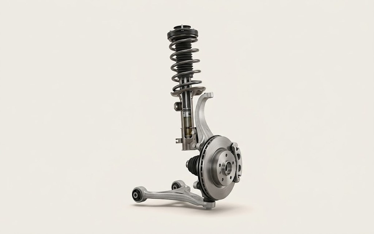 How it works · 3D
How Car Suspension Works
How the part you're working on actually works — in plain English, on a 3D model.
Open in 3D →