Autopapyrus · Renault Sandero (2nd generation)
https://autopapyrus.com/guides/renault/sandero/front-lower-control-arm-replacement/
https://autopapyrus.com/guides/renault/sandero/front-lower-control-arm-replacement/
Compiled automatically from service literature and owner experience. Specs are for the typical configuration — check them against your exact car before you start.
Renault Sandero (2nd generation): Front Lower Control Arm Replacement
On the Sandero II (B0 platform), the lower control arm is attached to the subframe by two bolts through bushings, and to the steering knuckle by a ball joint. If the bushings or ball joint are worn and the arm is not bent, it is simpler and more reliable to replace the complete arm assembly. It is best to replace the arms one at a time, but a wheel alignment check and adjustment are needed afterward.
Part
| № | Part | Alternatives |
|---|---|---|
| 01 | Front lower control arm with bushings and ball jointleft or right, depending on the side being replaced | Lemförder, TRW, Febi |
Tools
8- jack and jack stands
- lug wrench
- socket and wrench set (usually 16-21 mm)
- torque wrench
- pry bar or small crowbar
- grease
- wire brush
- penetrating oil. A ball joint separator is needed if the stud is stuck tight
 There's a full repair manual for this car
Every system, wiring diagrams and torque specs — not just this job. Haynes AutoFix (online).
See manuals →
Step by step
10 steps- Park the car on level ground, set the parking brake, and chock the rear wheels. Loosen the lug bolts on the side you are working on, but do not remove them yet.
- Lift the front of the car, place a jack stand under the body, and remove the wheel.
- Clean the arm's fasteners with a wire brush and treat them with penetrating oil. If the engine undertray or subframe guard is in the way, remove it.
- Remove the nut (or bolts) securing the ball joint to the steering knuckle. If there is a nut on the stud, hold the stud to keep it from turning. Pry the arm downward with a pry bar. If the stud does not come out, use a separator and do not strike the dust boot.
- Remove the nuts and bolts securing the arm to the subframe (front and rear bushings). Support the arm so it does not drop. Note the direction of the bolts, as you will need it during reassembly.
- Remove the arm. Compare it with the new one for length, shape, and ball joint position. Check the ball joint boot and bushings on the new part.
- Install the new arm. First insert the bolts through the subframe bushings and tighten them by hand. Then connect the ball joint to the knuckle.
- Tighten the ball joint and the arm-to-subframe fasteners. Torque values (for reference; verify exact values against the manufacturer's specifications): ball joint 40-60 N·m (30-44 lb-ft) (or per specification), bushing bolts 90-110 N·m (66-81 lb-ft). Do the final tightening of the bushing bolts only when the car is resting on its wheels. Otherwise the rubber bushings will be preloaded in a twisted state and will tear quickly.
- Install the wheel and snug the bolts, lower the car, and tighten the lug bolts in a crisscross pattern. The wheel torque is usually 100-130 N·m (74-96 lb-ft).
- Reinstall the guard if you removed it. Take a test drive, check for knocking noises, and recheck the tightness of the fasteners. Book a wheel alignment.
Common mistakes and warnings
- The suspension is a safety-critical system
- If you lack experience, or the threaded connections are seized and will not come loose, take the car to a repair shop
- Do not use bent arms or arms with cracks, and do not tighten the bushings while the suspension is hanging
- If the alignment is not adjusted after replacing the arm, uneven tire wear and pulling to one side may occur
- If only one side was replaced previously, check the condition of the arm on the other side
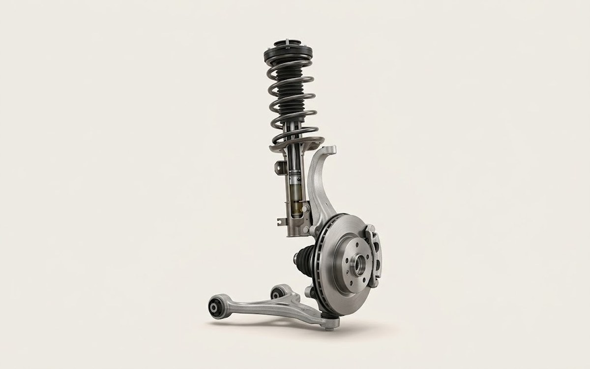 How it works · 3D
How Car Suspension Works
How the part you're working on actually works — in plain English, on a 3D model.
Open in 3D →