Autopapyrus · Mercedes-Benz A-Class (W176, 3rd generation)
https://autopapyrus.com/guides/mercedes-benz/a-class/front-lower-control-arm-bushing-replacement/
https://autopapyrus.com/guides/mercedes-benz/a-class/front-lower-control-arm-bushing-replacement/
Compiled automatically from service literature and owner experience. Specs are for the typical configuration — check them against your exact car before you start.
Mercedes-Benz A-Class (W176, 3rd generation): Front Lower Control Arm Bushing Replacement
On the W176, the front lower control arm attaches to the subframe with two bushings: a small front bushing and a large rear hydraulic bushing. The rear one works harder and wears out first. Signs of wear: knocking over bumps, a "floating" steering wheel under braking, uneven tire wear, and camber drifting out of specification. Replace the bushings in pairs, on both sides, and always get a wheel alignment afterward.
Parts
4| № | Part | Alternatives |
|---|---|---|
| 01 | Front lower control arm bushing, front (small)left and right | Lemförder, Meyle, Febi, Sachs |
| 02 | Front lower control arm bushing, rear (hydraulic, large)left and right | Lemförder, Meyle, Febi, Sachs |
| 03 | Suspension mounting bolts and nuts (torque-to-angle, single-use)replace with new | |
| 04 | Front lower control arm assembly with bushings and ball jointif pressing out the bushings isn't practical | Lemförder, Meyle, Febi, Sachs |
Tools
9- Jack and jack stands
- lug wrench
- socket and wrench set
- torque wrench
- pry bar
- ball joint separator or fork-type separator
- hydraulic press with adapters (or a bushing removal/installation kit)
- heat-resistant grease for the seating surfaces
- marks (marker, paint)
 There's a full repair manual for this car
Every system, wiring diagrams and torque specs — not just this job. Haynes and 7 more.
See manuals →
Step by step
14 steps- Park the car on level ground, loosen the lug nuts on the front wheels, lift the front of the car and set it on jack stands. Remove the wheels.
- Remove the engine undershield if it blocks access to the control arms and subframe.
- Inspect the control arm and mark the position of any eccentric or adjustment elements and the mounting bolts, if present. This will help preserve camber and toe until the alignment.
- Disconnect the control arm from the steering knuckle: remove the ball joint nut (if needed, hold the stud with a hex key or Torx bit), then press the stud out with a separator. Do not hit the stud, as you will damage the boot and the ball joint.
- If the sway bar link is in the way, disconnect it from the control arm or the strut, holding the link stud.
- Support the control arm with a jack. Remove the bolts securing the control arm to the subframe (front and rear bushings) and take the arm off the car. The suspension fasteners on the W176 are usually single-use or torque-to-angle, so do not reuse them.
- Secure the control arm in a vise or on the press. Press out the old bushings with a suitable adapter. If the rubber-metal bushing is seized, carefully heat the seat (do not overheat the rubber or the ball joint), or cut out the rubber and drive out the outer sleeve.
- Clean the bushing seats of rust and dirt, and check the metal of the arm for scoring and cracks. If the seat is damaged, it is better to replace the complete control arm.
- Press in the new bushings in the same orientation as the old ones (using the marks on the bushing and the position of the holes/slots). Press in the rear hydraulic bushing strictly along its axis and without tilting, pressing on the outer sleeve, not on the rubber.
- Install the control arm, insert the new bolts and nuts, and first tighten them by hand only, without final tightening.
- Load the suspension (place a jack under the arm or lower the car onto its wheels) and fully tighten the bolts securing the control arm to the subframe only when the suspension is at normal ride height with the car's weight on the wheels. This is important: tightening with the suspension hanging twists the rubber and quickly ruins the new bushings. Torque and angle must follow the manufacturer's specification for your version; for bolts like these it is typically 80-130 N·m (59-96 lb-ft) plus an angle turn.
- Connect the ball joint to the steering knuckle and tighten the nut (about 50-80 N·m (37-59 lb-ft); use the exact value from the specification). Install the sway bar link (about 40-60 N·m (30-44 lb-ft)) and the undershield.
- Install the wheels and tighten the lug nuts in a crisscross pattern to 130 N·m (96 lb-ft). Repeat the procedure on the other side.
- After reassembly, have a wheel alignment done at a shop and check the steering on a test drive. After 100-200 km, recheck the tightness of the main fasteners.
Common mistakes and warnings
- The front suspension is a safety-critical system
- If you lack experience and a press, leave pressing the bushings out and in to a repair shop: a tilted bushing or incorrect tightening will lead to rapid wear and loss of control
- Work only on rigid jack stands, never under a jack alone
- Do not reuse single-use bolts
- The exact torque values for this car are not confirmed in publicly available materials, so approximate ranges are given; verify the final values against the manufacturer's specification
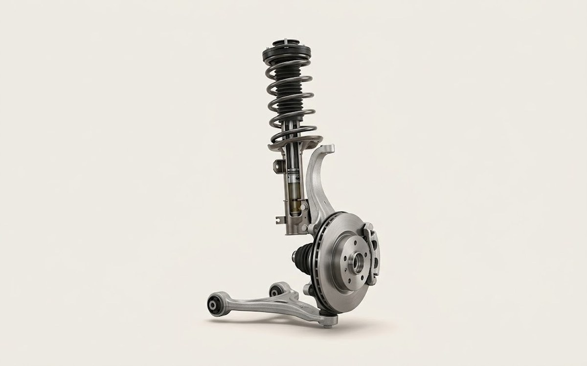 How it works · 3D
How Car Suspension Works
How the part you're working on actually works — in plain English, on a 3D model.
Open in 3D →