Autopapyrus · Hyundai Santa Fe IV (TM)
https://autopapyrus.com/guides/hyundai/santa-fe/front-lower-control-arm-replacement/
https://autopapyrus.com/guides/hyundai/santa-fe/front-lower-control-arm-replacement/
Compiled automatically from service literature and owner experience. Specs are for the typical configuration — check them against your exact car before you start.
Hyundai Santa Fe IV (TM): Front Lower Control Arm Replacement
The lower control arm is attached to the subframe with bolts and to the steering knuckle with a ball joint. Replace it if the bushings are worn or torn, the ball joint has play, or the arm is bent. The procedure is the same regardless of engine (including the 2.4 GDI). For 2021 (TM) vehicles, you need the arm for this specific generation. A wheel alignment is required after replacement.
Key figures
- Wheel nut torqueafter lowering the vehicle to the ground in step 12, using a torque wrench107.9-127.5 N·m (79.6-94.0 lb-ft)
- Ball joint nutstep 10, then always use a new cotter pin98.0-117.6 N·m (72.3-86.7 lb-ft)
- Arm-to-subframe boltsstep 13, tighten with the vehicle on its wheels156.9-176.5 N·m (115.7-130.2 lb-ft)
- Stabilizer link nutsteps 6 and 11, if the link was removed98.1-117.7 N·m (72.4-86.8 lb-ft)
Check these values against the manufacturer’s specification for your vehicle before you start.
Parts
2| № | Part |
|---|---|
| 01 | Front lower control arm assembly (with ball joint and bushings), left or right, for Santa Fe TM |
| 02 | new ball joint nut cotter pin. Aftermarket options: Lemforder, Sasic, Mobis. If only the bushing or ball joint is worn, they can be replaced separately, but on this generation the arm is normally replaced as a complete assembly |
Tools
10- jack and jack stands
- lug wrench
- socket set and open-end wrenches
- torque wrench (up to 200 N·m)
- ball joint separator
- hammer
- pry bar
- wire brush
- penetrating oil
- new cotter pin
 There's a full repair manual for this car
Every system, wiring diagrams and torque specs — not just this job. Haynes and 6 more.
See manuals →
Step by step
15 steps- Loosen the wheel nuts 1/2 turn while the vehicle is still on the ground. Park the vehicle on level ground, apply the parking brake, and chock the rear wheels.
- Raise the front of the vehicle, set it on sturdy jack stands, and remove the wheel. When reinstalling, tighten the wheel nuts to 107.9-127.5 N·m (79.6-94.0 lb-ft).
- Inspect the arm: spray penetrating oil on the subframe mounting bolts and the ball joint nut, and clean the threads with a wire brush.
- Remove the cotter pin from the ball joint nut and unscrew the nut. Do not drop it, and be careful not to damage the ball joint stud.
- Press the ball joint out of the steering knuckle. The factory procedure calls for a special puller: the support bolt is inserted through the arm bolt hole, the support body is installed on the driveshaft side, and then the tension bolt is tightened. A universal ball joint separator will work as long as it does not damage the boot. Do not hit the stud with a hammer without the nut installed to protect the threads.
- If the stabilizer bar or link is in the way, disconnect the stabilizer link from the arm (hold the stud by its outer hex and do not tear the boot). The stabilizer link nut torque on the TM is 98.1-117.7 N·m (72.4-86.8 lb-ft).
- Remove the bolts securing the arm to the subframe, supporting the arm by hand, and remove it. Note the position and direction of the bolts.
- Compare the new arm with the old one (left/right, length, ball joint position). Check that the boot is intact.
- Install the arm into the subframe and insert the bolts, leaving them loose for now. Do the final tightening with the suspension loaded (vehicle on its wheels), otherwise the bushings will be twisted and will fail quickly. The factory page does not include this instruction, but it is common practice for rubber bushings.
- Insert the ball joint stud into the knuckle, tighten the nut to 98.0-117.6 N·m (72.3-86.7 lb-ft), and secure it with a new cotter pin (tightening the nut slightly further if needed to align the slot).
- Reconnect the stabilizer link (if removed), torque 98.1-117.7 N·m (72.4-86.8 lb-ft).
- Install the wheel, hand-tighten the nuts in a crisscross pattern, lower the vehicle to the ground, and tighten the wheel nuts with a torque wrench to 107.9-127.5 N·m (79.6-94.0 lb-ft).
- Tighten the arm-to-subframe bolts to 156.9-176.5 N·m (115.7-130.2 lb-ft) with the vehicle on its wheels.
- Check that the boots and cotter pins are in place and that nothing contacts the driveshaft or brake hose. Take a test drive at low speed and check for knocking noises.
- Be sure to get a wheel alignment: the wheel alignment angles change after replacing the arm.
Common mistakes and warnings
- The suspension is a safety-critical system: an incorrectly tightened ball joint or arm bolts can lead to loss of control
- If you have no experience working on suspensions and with a torque wrench, leave the job to a repair shop
- Torque specifications are taken from factory data for the Santa Fe TM, but double-check them against the manufacturer's manual for your trim
- Never work under a vehicle supported only by a jack
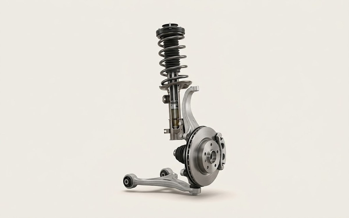 How it works · 3D
How Car Suspension Works
How the part you're working on actually works — in plain English, on a 3D model.
Open in 3D →