Autopapyrus · Tesla Model Y (2022)
https://autopapyrus.com/catalog/tesla/model-y/guides/front-upper-control-arm-replacement/
https://autopapyrus.com/catalog/tesla/model-y/guides/front-upper-control-arm-replacement/
Compiled automatically from service literature and owner experience. Specs are for the typical configuration — check them against your exact car before you start.
Tesla Model Y (2022): Front Upper Control Arm Replacement
The arm is removed together with its bracket, which is attached to the body with four bolts. The arm is then separated from the bracket by two bolts. This guide covers the left side; the right side follows the same procedure. A wheel alignment check and adjustment is required after replacement.
Key figures
- Arm-to-bracket bolts50 N·m (37 lb-ft). Tighten with a torque wrench and a deep 13 mm socket, with the arm positioned using the gauge (step 14)
- Bracket-to-body bolts, 15 mm62 N·m (46 lb-ft). Two large bolts, install at the marks (step 17)
- Bracket-to-body bolts, 13 mm34 N·m (25 lb-ft). Two smaller bolts (step 18)
- Sway bar link nut98 N·m (72 lb-ft). New nut, hold the ball stud (step 19)
- Arm-to-steering-knuckle nut56 N·m (41 lb-ft). New nut, 15 mm socket and Torx T50 (step 20)
Check these values against the manufacturer’s specification for your vehicle before you start.
Parts
3| № | Part | Alternatives |
|---|---|---|
| 01 | Front upper control arm for Model Y (with ball joint and bushings)left or rightFind on Amazon → | AlternativesMeyleSidemSuperPro |
| 02 | Arm-to-steering-knuckle nut (new)Find on Amazon → | |
| 03 | Sway bar link stud nut (new)sway bar link to strut mountFind on Amazon → |
Amazon links search by the part name; use Amazon's fit check for your car before ordering. We may earn a commission from qualifying purchases.
Tools
10- Jack or two-post lift Amazon →
- 13 Amazon →
- 15 and 18 mm sockets (deep 13 mm socket) Amazon →
- Torx T40 and T50 bits/sockets Amazon →
- torque wrench Amazon →
- ratchet with a swivel joint Amazon →
- pry bar Amazon →
- marker or paint Amazon →
- blanket or rag to protect the wheel well liner Amazon →
- alignment tool for checking arm position during tightening (factory tool: upper arm height gauge) Amazon →
Step by step
26 steps · 4 stagesStage 1 of 4 Preparation 4 steps
- Inspect the tires for uneven wear. It will show whether the wheel alignment was already off before the replacement. Keep this in mind for the check after the replacement.
- Put the vehicle on a lift, or on a jack on level ground. Make sure the vehicle is not charging. The suspension unloads when the arm is removed, so the vehicle must rest securely on its supports.
- Remove the front wheel on the side you are working on.
- Remove the cabin air filter housing (HEPA). You need it out of the way to reach the fasteners.
Stage 2 of 4 Removal 7 steps
- Release the two clips that hold the wheel speed sensor harness to the arm, and move the harness aside.
- Remove the nut that secures the sway bar link to the strut, and pull the link out of the strut. Hold the ball stud so it does not turn (Torx T40), and loosen the nut with an 18 mm socket. Use a pry bar if needed. Discard the nut, since it is single-use.
- While supporting the steering knuckle so it does not fall, push the arm's ball joint down and drive out or pull out the arm-to-knuckle bolt (15 mm socket and Torx T50). Discard the nut.
- Mark with a marker the position of the four bolts that secure the arm bracket to the body (two 13 mm and two 15 mm). Then remove them. The bolts differ in length and size, so note which one goes where.
- Cover the arm bracket with a cloth so it does not scratch the wheel well liner.
- Pull the strut assembly outward so the arm bracket can clear the wheel well liner. Guide the right-hand part of the arm through first, holding the bracket and moving the liner aside with your fingers.
- Remove the two bolts that secure the arm to the bracket (deep 13 mm socket) and take off the arm.
Stage 3 of 4 Installation 10 steps
- Compare the new arm with the old one: side, length, and the position of the ball joint and bushings.
- Insert the arm into the bracket and thread in the two arm-to-bracket bolts by hand.
- Set the arm position relative to the bracket using the factory arm height gauge. It mounts on the bracket at the rear outer mounting hole, and the arm is pressed against its plate. Tighten the two arm-to-bracket bolts to 50 N·m (37 lb-ft). Watch the position of your hand and the tool while tightening. After tightening, check the measurement again.
- Remove the gauge.
- Guide the bracket with the arm into place, lining up the bolt holes with the holes in the body. Remove the cloth.
- Install the two 15 mm bolts that secure the bracket to the body and tighten them to 62 N·m (46 lb-ft). Line them up with the marks you made during removal. Do not mix up the large and small bolts.
- Install the two 13 mm bolts that secure the bracket to the body and tighten them to 34 N·m (25 lb-ft).
- Fit the sway bar link onto the strut, install a new nut, and tighten it to 98 N·m (72 lb-ft). Hold the ball stud.
- Line up the arm with the knuckle, insert the bolt, thread on a new nut, and tighten it to 56 N·m (41 lb-ft).
- Secure the wheel speed sensor harness to the arm with the clips.
Stage 4 of 4 Reassembly and check 5 steps
- Install the cabin air filter housing (HEPA).
- Install the wheel and tighten the lug nuts in a crisscross pattern to the manufacturer's specification.
- Lower the vehicle onto its wheels. Check that the sensor harness is not stretched and that the sway bar link and ball joint have no play.
- Take a test drive at low speed: check for knocking, pulling, and steering wheel vibration.
- Check the wheel alignment (camber and toe) on an alignment rack and adjust it if needed. This is mandatory after replacing the upper arm.
Common mistakes and warnings
- The suspension and steering are safety-critical systems
- If you have no experience working on suspension, have a repair shop do the replacement
- Never leave suspension fasteners under-tightened
- Do not reuse the single-use nuts (arm to knuckle, sway bar link)
- If the replacement is being done after an impact or accident, also check the condition of the steering rack and the body geometry
- If the vehicle is on a jack, always back it up with jack stands
- Opinions on tightening differ: third-party instructions recommend final-tightening the fasteners with the vehicle on its wheels
- The factory manual describes tightening the arm bolts using the gauge, as in the steps above
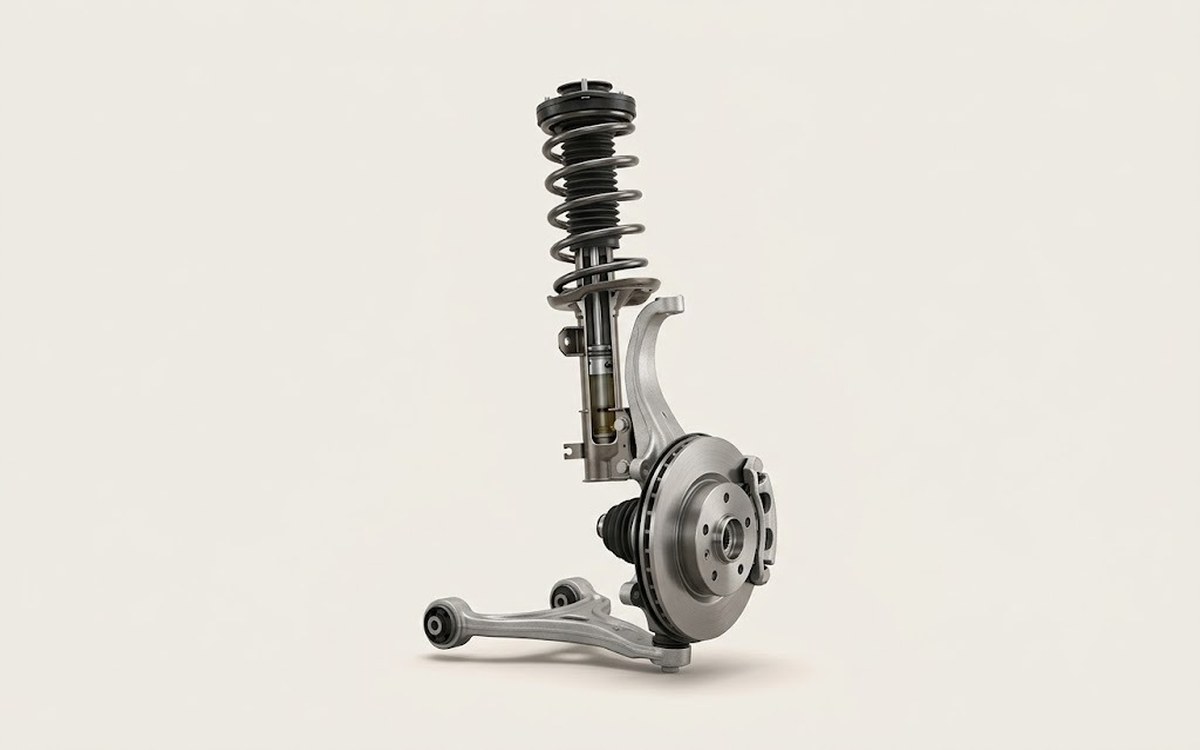 How it works · 3D
How Car Suspension Works
How the part you're working on actually works — in plain English, on a 3D model.
Open in 3D →
Spotted a mistake? Tell us →
Our articles
 Brand stories
The History of the Tesla Brand
Tesla Motors, a North American company founded in 2003, is rightly considered the pioneer of a new era in the…
Read →
 Garage
Fuel Quality Indicators: What Octane and Cetane Numbers Mean
What is an octane number? What about a cetane number? Which fuel should you choose for a high-compression engine?…
Read →
 Before you buy
How to Pick Up Your Car from the Dealership the Right Way
If you've decided to buy a car from a dealership, it isn't enough to simply choose a model you like, pay for it, and…
Read →