Autopapyrus · Haval M6
https://autopapyrus.com/guides/haval/m6/replacing-the-rear-control-arms-and-bushings-on-a-haval-m6-2nd-generation/
https://autopapyrus.com/guides/haval/m6/replacing-the-rear-control-arms-and-bushings-on-a-haval-m6-2nd-generation/
Compiled automatically from service literature and owner experience. Specs are for the typical configuration — check them against your exact car before you start.
Replacing the Rear Control Arms and Bushings on a Haval M6 (2nd Generation)
The rear suspension on the 2nd-generation Haval M6 is an independent multi-link design. The arms attach to the subframe and the steering knuckle with bolts, often with eccentric bolts for camber and toe adjustment. The exact procedure and torque specifications for this model are not documented in open sources, so what follows is the general approach for this type of suspension. Check all torque values against the manufacturer's service manual.
Parts
6| № | Part | Alternatives |
|---|---|---|
| 01 | Rear upper control armleft and right, matched to position | Lemforder, Sasic, TRW |
| 02 | Rear lower control armleft and right, matched to position | Lemforder, Sasic, TRW |
| 03 | Rear trailing armif needed | Lemforder, Sasic, TRW |
| 04 | Rear camber/toe adjusting linkif needed | Lemforder, Sasic, TRW |
| 05 | Rear control arm bushingsif the arm is sold separately from the bushings | Lemforder, Sasic, TRW |
| 06 | Control arm bolt and self-locking nut setif single-use |
Tools
11- Lift or jack with rigid jack stands
- wheel chocks
- lug wrench
- torque wrench
- socket and wrench set (usually 17-24 mm)
- ratchet with extension
- drift punch and hammer
- penetrating oil
- bushing puller or press
- second jack (or a transmission jack) to support the arm or hub
- chalk or marker
Step by step
12 steps- Park the vehicle on level ground, apply the parking brake, and place chocks under the front wheels. Loosen the lug nuts on the rear wheel, raise the rear of the vehicle, and set it on rigid jack stands. Remove the wheel.
- Inspect the suspension and locate the arm you need to replace. Check the arms for play with a pry bar and inspect the bushings for cracks and tears. Decide which arm needs replacing, and mark the position of the eccentrics (bolts with cam washers) with chalk or a marker to preserve the camber and toe settings.
- Apply penetrating oil to the threaded fasteners and wait 10-15 minutes. If the ride height sensor or the ABS sensor wiring is in the way, carefully disconnect the connectors and remove the brackets.
- Position a second jack under the hub or the lower arm and lightly support the assembly. If you are removing the lower arm, the spring or shock absorber may be under load, so do not let the suspension drop suddenly.
- Remove the nuts and drive out the arm bolts on the knuckle side and the subframe side. Note the position and orientation of the bolts and washers. If a bolt is seized, heat it and drive it out with a drift punch.
- Remove the arm. Compare the old and new arms for length, shape, and bushing locations.
- If you are replacing only the bushings, press them out with a puller or a press. Do not heat the rubber part with an open flame, and do not cut out the bushing seat with a hacksaw unless necessary. Clean the bore of dirt and rust, then press in the new bushing straight, without tilting, until it seats fully. Lubricate only with silicone grease, not with oil or gasoline-based products.
- If the subframe bushings are worn, that is a separate and more difficult job: you will need to support or partially lower the subframe. It takes experience and is best done at a repair shop.
- Install the arm, insert the bolts in their original positions, and thread the nuts on by hand. Do the final tightening with the suspension loaded (or with the hub raised by a jack to the normal ride-height position). If you tighten the bushings while the suspension is hanging, the rubber will be twisted in service and will tear quickly.
- Reinstall the sensors and connectors. Mount the wheel and tighten the lug nuts in a crisscross pattern. As a rough guide for wheels in this class, 110-130 N·m (81-96 lb-ft); check the exact value in the manufacturer's service manual. Lower the vehicle.
- Tighten the arm bolts with a torque wrench with the vehicle on the ground. Torque values for arm bolts in this class usually fall in the range of 80-150 N·m (59-111 lb-ft), depending on the bolt (check the exact values in the manufacturer's service manual). Use your marks to confirm the eccentrics are in their original positions.
- Drive the vehicle 100-200 m (330-660 ft), listen for unusual noises, and check the tightness. Be sure to have the camber and toe aligned on an alignment rack: the geometry changes after replacing arms and eccentrics.
Common mistakes and warnings
- The suspension is a safety-critical system
- Incorrect tightening or mismatched parts can lead to loss of vehicle control
- If you lack experience, leave the job to a repair shop
- Do not work under a vehicle supported only by a jack
- It is best to replace arms in pairs (on both sides), and always have the alignment checked after replacement
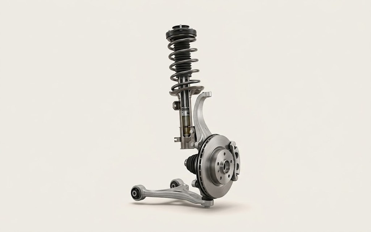 How it works · 3D
How Car Suspension Works
How the part you're working on actually works — in plain English, on a 3D model.
Open in 3D →