Autopapyrus · Tesla Model X (2019)
https://autopapyrus.com/catalog/tesla/model-x/guides/front-upper-control-arm-replacement/
https://autopapyrus.com/catalog/tesla/model-x/guides/front-upper-control-arm-replacement/
Compiled automatically from service literature and owner experience. Specs are for the typical configuration — check them against your exact car before you start.
Tesla Model X (2019): Front Upper Control Arm Replacement
The upper control arm connects the steering knuckle to the body and sets the wheel's camber and caster. This guide covers the left side. On the right side, only access differs: you don't need to move the front trunk fuse box, but you do need to disconnect the ride height sensor. The procedure is different for the rear axle and the lower control arms.
Key figures
- Tightening the two bolts that secure the arm to the bodytighten only with the ride height locking tool (step 21)68 N·m (50 lb-ft)
- Tightening the ball joint bolt and nut in the knucklebolt and nut are new, turn the nut, hold the bolt (step 23)60 N·m (44 lb-ft)
- Tightening the ride height sensor arm nutlow torque, don't strip the threads (step 26)7 N·m (5 lb-ft)
- Tightening the pump support bracket boltsduring installation (step 25)10 N·m (7 lb-ft)
- Tightening the pump bracket boltduring installation (step 25)5 N·m (4 lb-ft)
Check these values against the manufacturer’s specification for your vehicle before you start.
Parts
4| № | Part | Alternatives |
|---|---|---|
| 01 | Front upper control arm for Model X 2015left or rightFind on Amazon → | AlternativesFebi |
| 02 | Ball joint-to-steering knuckle bolt (single-use, new)Find on Amazon → | |
| 03 | Ball joint-to-steering knuckle nut (single-use, new)Find on Amazon → | |
| 04 | Arm-to-body bolt2 pcsFind on Amazon → |
Amazon links search by the part name; use Amazon's fit check for your car before ordering. We may earn a commission from qualifying purchases.
Tools
7Step by step
31 steps · 7 stagesStage 1 of 7 Preparation 3 steps
- Park the vehicle on level ground and turn it off. On the touchscreen, enable Jack Mode so the air suspension doesn't change height while you work.
- Raise the front of the vehicle on a lift or with a jack at the designated lift points, and set it on jack stands. Remove the front wheel on the side you're working on.
- If the vehicle has been in a collision, check beforehand whether the steering rack has been damaged: if the suspension is deformed, the rack may also need to be replaced.
Stage 2 of 7 Access (left side) 6 steps
- Remove the HEPA filter housing in the front trunk.
- Release the 4 clips on the front trunk fuse box, slide the box up, then forward.
- Remove the 3 bolts of the fuse box bracket located under the hood. Tightening torque during installation is 7 N·m (5 lb-ft).
- Carefully move the fuse box to the right, without straining the wiring harnesses.
- Remove the front left wheel well liner.
- Remove the nut that holds the ride height sensor arm on the upper control arm. Torque during installation is 7 N·m (5 lb-ft).
Stage 3 of 7 Access to the rear arm bolt 4 steps
- Through the wheel well, disconnect the connector of powertrain coolant pump No. 2, move the pump up, and remove it from the bracket.
- Remove the bolt that holds the pump bracket to the support bracket (5 N·m (4 lb-ft) during installation), and remove the pump bracket.
- Release the harness clip on the inner upper part of the support bracket.
- Remove the bolts securing the support bracket to the body (10 N·m (7 lb-ft) during installation) and remove the support bracket. The rear arm bolt is now exposed.
Stage 4 of 7 Arm removal 4 steps
- Release the rubber grommets that secure the wheel speed sensor harness to the body and to the steering knuckle.
- Remove and discard the bolt and nut that secure the ball joint to the knuckle. While turning the nut, hold the bolt with a second wrench.
- Pull the ball joint out of the steering knuckle. Support the knuckle so it doesn't hang on the axle and hoses.
- Remove the 2 bolts securing the arm to the body, and remove the arm.
Stage 5 of 7 Installation 7 steps
- Wipe the mounting surfaces on the body and on the knuckle, and compare the new arm with the old one (side, length, ball joint position).
- Install the arm and thread in the 2 arm-to-body bolts by hand, without tightening them yet.
- Attach the ride height locking special tool (FUCA ride height tool) to the upper control arm and the body. Before that, clean the dirt out of the shock tower well so the tool's profile seats evenly.
- Tighten the 2 arm-to-body bolts to 68 N·m (50 lb-ft).
- Remove the special tool.
- Insert the ball joint into the knuckle, install the new bolt and nut, and tighten to 60 N·m (44 lb-ft) (hold the bolt and apply the torque to the nut).
- Secure the wheel speed sensor harness in the grommets on the body and knuckle.
Stage 6 of 7 Reassembly 4 steps
- Reinstall the pump support bracket (bolts 10 N·m (7 lb-ft)), the pump bracket (bolt 5 N·m (4 lb-ft)), and the pump, connect the connector, and secure the harness with the clip.
- Install the ride height sensor arm on the upper control arm and tighten the nut to 7 N·m (5 lb-ft).
- Put the fuse box back in place: bracket on 3 bolts (7 N·m (5 lb-ft)), snap the box in with the 4 clips.
- Install the wheel well liner, the HEPA filter housing, and the wheel (lug nut torque per the manufacturer's specification), then lower the vehicle.
Stage 7 of 7 Check 3 steps
- Turn off Jack Mode and let the suspension settle to normal ride height. Make sure there are no suspension or steering errors on the screen.
- Take a test drive at low speed: there should be no knocking, the steering wheel should be straight, and the vehicle should not pull to either side.
- After replacing the arm, be sure to have a wheel alignment check and adjustment done on an alignment rack (camber, toe), and also have the power steering checked per Tesla's procedure.
Common mistakes and warnings
- This job involves the suspension and steering, so if you lack experience, leave it to a repair shop
- Do not tighten the arm bolts with the suspension hanging without the ride height locking tool: wheel angles and tire life depend on it
- Use only a new ball joint bolt and nut
- You aren't touching the high-voltage system, but do not open the orange power cables or components
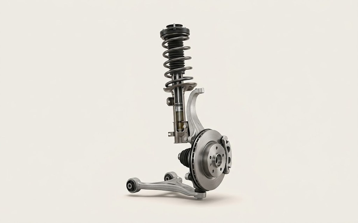 How it works · 3D
How Car Suspension Works
How the part you're working on actually works — in plain English, on a 3D model.
Open in 3D →
Spotted a mistake? Tell us →
Our articles
 Brand stories
The History of the Tesla Brand
Tesla Motors, a North American company founded in 2003, is rightly considered the pioneer of a new era in the…
Read →
 Garage
Fuel Quality Indicators: What Octane and Cetane Numbers Mean
What is an octane number? What about a cetane number? Which fuel should you choose for a high-compression engine?…
Read →
 Before you buy
How to Pick Up Your Car from the Dealership the Right Way
If you've decided to buy a car from a dealership, it isn't enough to simply choose a model you like, pay for it, and…
Read →